Leveling Mower Deck
 CAUTION: Rotating blades are dangerous. Before adjusting or
servicing mower:
CAUTION: Rotating blades are dangerous. Before adjusting or
servicing mower:
• Disconnect spark plug wire(s) or battery negative (-) cable to prevent engine from starting accidently.
• Always wear gloves when handling mower blades or working near blades.
-
Park machine safely. (See Parking Safely in the SAFETY section.)
-
Inflate tires to the correct pressure.
-
Set deck to the transport position.
- The transport position is the 127 mm (5 in.) cutting height position.
-
Inspect mower blades for:
- Blade sharpness.
- Blade damage.
- Bent blades.
Checking Level (Side-to-Side)
NOTE: Mower deck anti-scalp wheels should not contact the ground.
-
Set cutting height to 76 mm (3 in.) position.
-
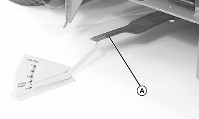
TCAL43759-UN-21MAR13Discharge chute raised for photo clarity.
Position right mower blade (A) (discharge side) in the side-to-side position. -
NOTE: Use a short ruler or a leveling gauge to check the mower blade level.
Measure from outside blade tip to the ground.
-
Position left mower blade in the sideways (left to right) position.
-
Measure from outside blade tip to the ground.
- The difference between both measurements should be no greater than 3 mm (1/8 in.).
-
If side-to-side level is not within the given tolerance, an adjustment is necessary.
Adjusting Level (Side-to-Side)
-
Set deck to transport position.
- The transport position is the 127 mm (5 in.) cutting height position.
-
Place 76 mm (3 in.) wooden blocks (B) under each side of the mower deck.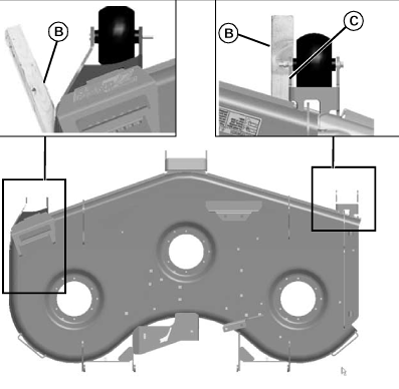
TCAL43760-UN-21MAR13- The wooden block placed under the left side of the mower deck must be positioned to the rear of the raised portion of the deck wall.
NOTE: The right front anti-scalp wheel must not rest on the wooden block.
- The wooden block placed under the right side of the mower deck must be positioned under the right front anti-scalp wheel bracket (C).
-
Lower mower deck down onto the wooden blocks.
-
Set height-of-cut to 83 mm (3-1/4 in.).
-
Verify that cam follower located on rear lift shaft is in contact with height adjustment cam on lift system.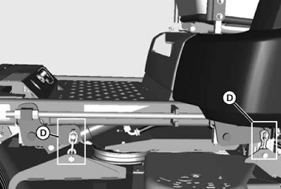
TCAL43761-UN-21MAR13 -
Adjust front and rear chain lengths (D) on each side of machine so there is no slack in links and deck is freely supported by the 76 mm (3 in.) wooden blocks.
-
Set deck to the transport position.
- The transport position is the 127 mm (5 in.) cutting height position.
-
Remove wooden blocks from under both sides of the mower deck.
-
Set deck to 76 mm (3 in.) cutting height position.
-
Check side-to-side mower level. Repeat adjustment as needed.
Checking Level (Front-to-Rear)
-
Set deck to the 76 mm (3 in.) cutting height position.
-
Position right mower blade (discharge side) in the straight forward (front-to-rear) position.
-
Measure from the right front blade tip to the ground.
-
Turn blade 180° and measure from right rear blade tip to the ground.
-
The height (E) of the rear blade tip should be between 3 - 6 mm (1/8 - 1/4 in.) higher than the front blade tip.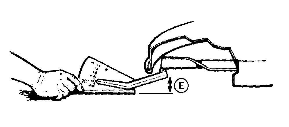
TCAL43762-UN-21MAR13
-
-
If the front-to-rear level is not within the given tolerance, an adjustment is necessary.
Adjusting Level (Front-to-Rear)
IMPORTANT: Adjust the left and right deck lift assist rods equally.
NOTE: Adjust side-to-side mower level before adjusting front-to-rear level.
Adjust both sides of the mower deck equally.
-
Loosen jam nut (F) on each deck lift assist rod.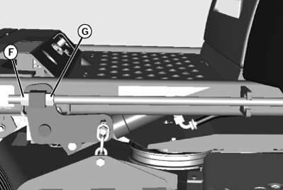
TCAL43763-UN-21MAR13 -
While positioned in front of the machine, adjust mower level:
- Turn hex nut (G) counterclockwise to lower front of mower deck.
- Turn hex nut (G) clockwise to raise front of mower deck.
-
Verify that the adjustment on right and left sides is equal.
-
Tighten jam nuts.
-
Check front-to-rear mower level.
|
DK75838,00006C7-19-20130326 |