Adjusting Cutting Height/Tailwheel Position (Lift-Type)1. Position machine on flat level ground. 2. Raise cutter. |
AG,OUMX005,1025 -19-09AUG99-1/5 |
|
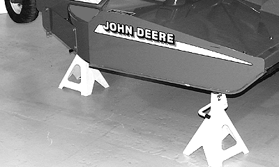
3. Place safety shop stands under cutter. 4. Lower cutter onto stands. |
|
AG,OUMX005,1025 -19-09AUG99-2/5 |
|
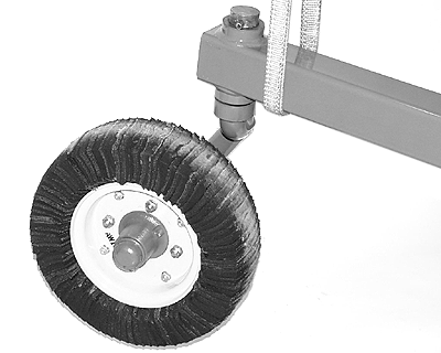
5. Wrap a lifting strap around axle support tube and attach to a hoist. |
|
AG,OUMX005,1025 -19-09AUG99-3/5 |

|
|
|
|
|
|
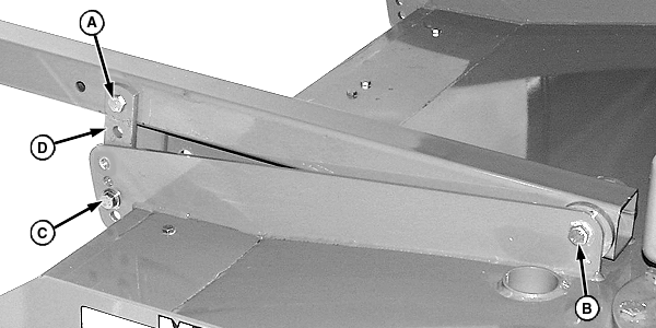
6. Loosen lock nut and cap screw (B). 7. Remove two cap screws and lock nuts (C). |
8. Remove lock nut and cap screw (A) and straps (D), if necessary. |
AG,OUMX005,1025 -19-09AUG99-4/5 |

|
|
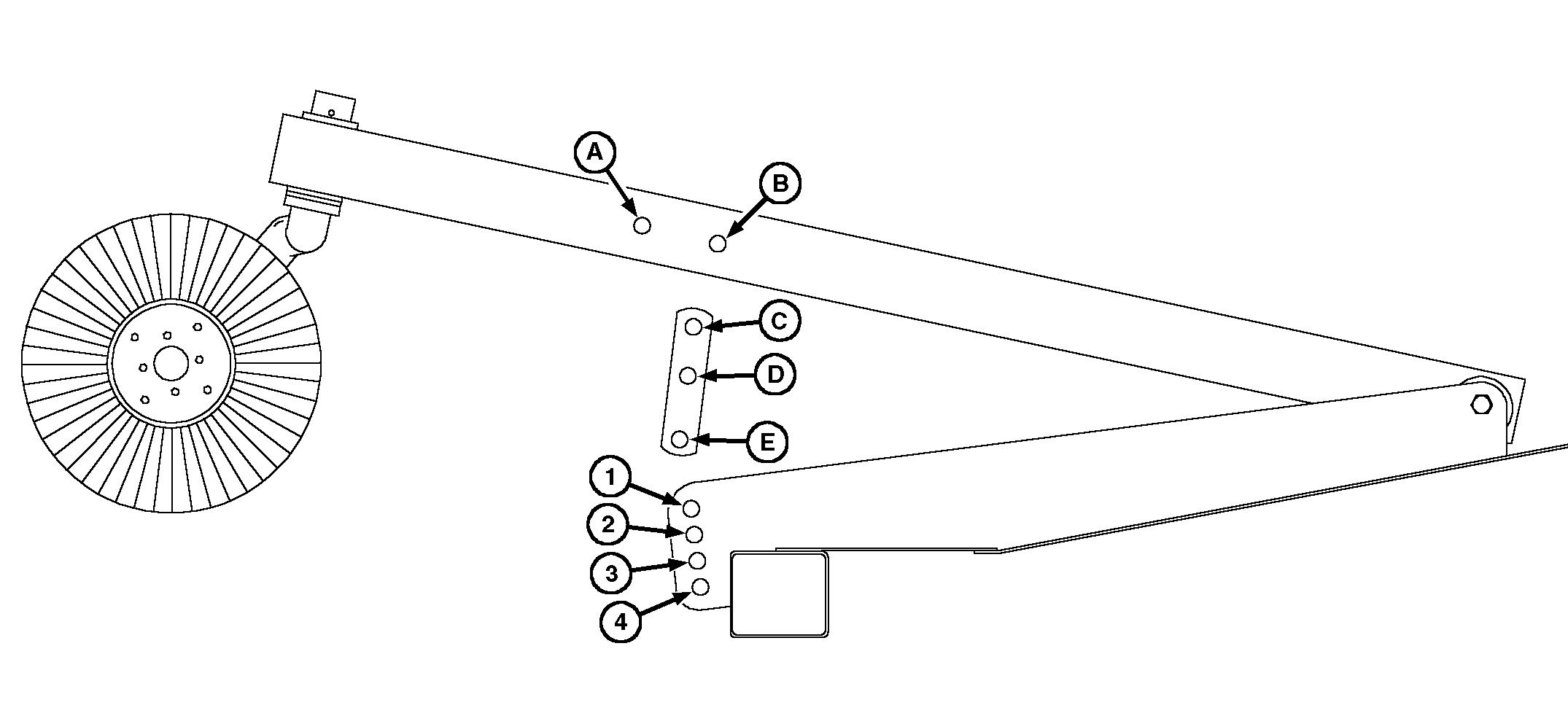
9. Raise or lower axle support tube and position straps to desired cutting height/position according to chart.
|
10. Re-install cap screws and lock nuts. Tighten all lock nuts. 11. Repeat on opposite side. |
||||||||||||||||||||||
AG,OUMX005,1025 -19-09AUG99-5/5 |
 CAUTION:
Be sure to support cutter frame at all four corner locations with safety shop stands to prevent accidental lowering. Do not position safety stands under axle or wheel supports because these components can rotate.

