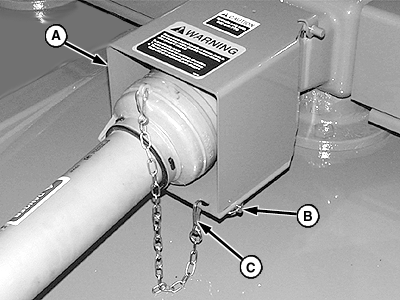
Removing and Installing PTO Driveline-Lift-Type and Semi-Mount1. Disconnect chain (C). 2. Remove two quick-lock pins (B) and raise PTO shield (A).
|
|
AG,OUMX005,1026 -19-09AUG99-1/2 |
|
NOTE: Driveline removed for illustration purposes. 3. Remove lock nut (B) and washer (C). 4. Remove tapered pin (A) using a brass drift and hammer. 5. Remove driveline assembly from gear case input shaft. 6. Make repairs as necessary:
7. Install driveline in reverse order of removal using the following special instructions:
Specification
|
|
AG,OUMX005,1026 -19-09AUG99-2/2 |

