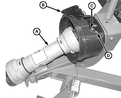
Removing and Installing PTO Drivelines-Pull-Type1. Remove cover (B). 2. Remove lock nut, washer and tapered pin (C). Remove tapered pin using a brass drift and hammer. 3. Remove main driveline (A) from intermediate driveline shaft. 4. Remove spacer (D).
|
|
AG,OUMX005,1027 -19-09AUG99-1/4 |
|
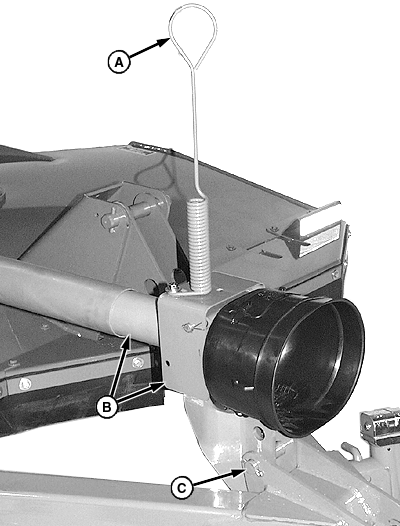
5. Remove hydraulic hose from holder (A). 6. Support pedestal and remove cotter pin and pin (C). 7. Remove pedestal and front half of intermediate driveline (B).
|
|
AG,OUMX005,1027 -19-09AUG99-2/4 |
|
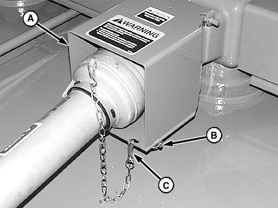
8. Disconnect chain (C). 9. Remove two quick-lock pins (B) and raise PTO shield (A).
|
|
AG,OUMX005,1027 -19-09AUG99-3/4 |
|
NOTE: Driveline removed for illustration purposes. 10. Remove lock nut (B) and washer (C). 11. Remove tapered pin (A) using a brass drift and hammer. 12. Remove driveline and pedestal assembly from gear case input shaft. 13. Make repairs as necessary:
14. Install drivelines in reverse order of removal using the following special instructions:
Specification
|
|
AG,OUMX005,1027 -19-09AUG99-4/4 |


