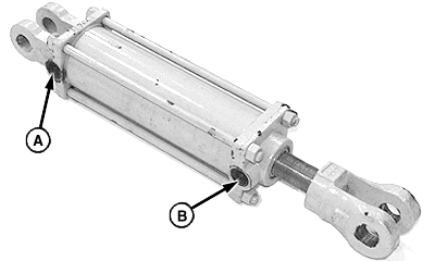
Assemble and Install Lift Cylinder and Hose1. Remove and discard shipping plug and O-ring from port (B). 2. Remove and save orifice from port (B). 3. Remove and save vent/plug and O-ring from port (A). 4. Remove cotter pins and pins from ends of cylinder. Discard one pin. |
|
AG,OUMX005,814 -19-03JUN99-1/5 |
|
|
|
|
|
|
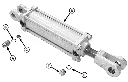
5. Install existing orifice (C), O-ring (B) and straight fitting (A) in base end port. Install fitting with flare end away from cylinder, as shown. |
6. Install existing O-ring (E) and vent/plug (F) in rod end port. |
AG,OUMX005,814 -19-03JUN99-2/5 |
|
|
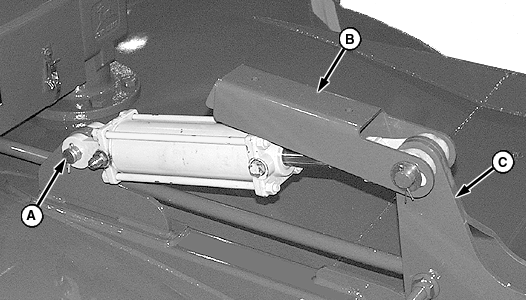
7. Align base end of cylinder with hole in tab on top of cutter. Install existing headed pin and cotter pin (A). 8. Align rod end of cylinder with pivoting bracket (C). Insert 25 x 112 mm pin through cylinder lock (B), rod end of cylinder and bracket. |
9. Install one 1-1/32 x 1-3/4 x 0.105 in. washer on each end of pin. Retain with 4 x 40 mm cotter pins. |
AG,OUMX005,814 -19-03JUN99-3/5 |
|
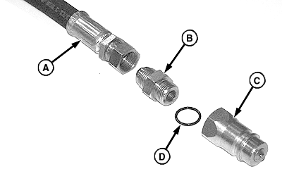
10. Assemble coupler (C), O-ring (D) and straight fitting (B) onto end of hydraulic hose (A). Install fitting with flare end toward hose, as shown.
|
|
AG,OUMX005,814 -19-03JUN99-4/5 |
|
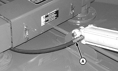
11. Connect opposite end of hydraulic hose (A) to fitting on lift cylinder. 12. Route coupler end of hose under driveline toward front of cutter.
|
|
AG,OUMX005,814 -19-03JUN99-5/5 |
