Install PTO Driveline1. Remove lock nut (B), washer (C) and tapered pin (A) from slip clutch hub.
|
|
AG,OUMX005,821 -19-03JUN99-1/5 |
|
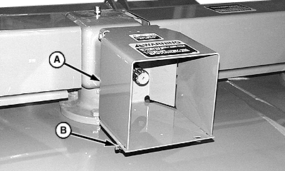
2. Remove two quick-lock pins (B) and raise PTO shield (A). 3. Remove paint from gear case input shaft using a wire brush. 4. Apply multipurpose grease on input shaft.
|
|
AG,OUMX005,821 -19-03JUN99-2/5 |
|
5. Align splines of slip clutch hub with gear case input shaft and slide hub onto shaft. 6. Align hole in hub with groove in input shaft and install tapered pin, washer and lock nut (A). Install tapered part of pin facing groove around input shaft. Tighten lock nut to specifications. Specification
7. Remove 5 mm hex wrench (provided) from side of driveline. 8. Adjust four set screws (B) to the desired setting:
|
|
AG,OUMX005,821 -19-03JUN99-3/5 |
|
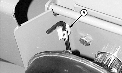
9. Attach clip (A) inside PTO shield, on right-hand side, away from clutch. Store hex wrench in clip.
|
|
AG,OUMX005,821 -19-03JUN99-4/5 |
|
10. Lower PTO shield and install quick-lock pins. 11. Attach chain (A) at location shown. |
|
AG,OUMX005,821 -19-03JUN99-5/5 |


