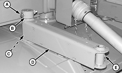
Install Hitch Arms and HitchNOTE: MX10 is shown throughout procedure. MX8 is similar. Left-hand hitch arm has mounting tabs for offset cylinder. Installation procedures are the same for both. 1. Apply multipurpose grease to pivot post (C). 2. Install hitch arm (D) with lubrication fitting (E) facing toward center of machine. 3. Install 71 x 89 x 50 mm bushing (B), M20 x 100 mm cap screw (A) and lock nut. 4. Repeat on left-hand side. |
|
AG,OUMX005,826 -19-03JUN99-1/3 |

|
|
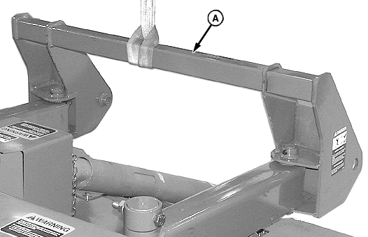
5. Wrap a lifting strap around hitch (A) and attach to a hoist. |
6. Position hitch over arms as shown. |
AG,OUMX005,826 -19-03JUN99-2/3 |
|
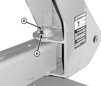
7. Apply multipurpose grease to 35 x 202 mm pins (A). 8. Align holes in hitch and arms and install pins using a brass drift and hammer. 9. Install 10 x 58 mm drilled pins (B) and 3.2 x 25 mm cotter pins. 10. Remove lifting strap.
|
|
AG,OUMX005,826 -19-03JUN99-3/3 |

