Assemble and Install Offset Cylinder and Hoses
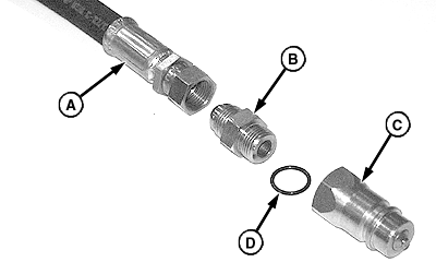
NOTE: Offset cylinder is equipped with two hydraulic hoses. Perform the following procedure on both hose assemblies. 1. Assemble coupler (C), O-ring (D) and straight fitting (B) onto end of hydraulic hose (A). Install fitting with flare end toward hose, as shown.
|
|
AG,OUMX005,827 -19-09JUL99-1/5 |
|
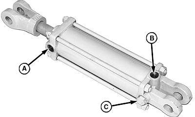
2. Remove and discard shipping plug, O-ring and orifice from port (A). 3. Remove and discard vent/plug and O-ring from port (C). 4. Remove shipping plug and O-ring from port (B) and install in port (C). 5. Remove cotter pins and pins from ends of cylinder. Discard one pin. |
|
AG,OUMX005,827 -19-09JUL99-2/5 |
|
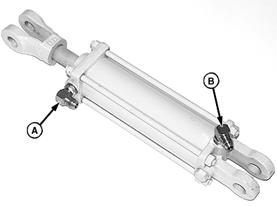
6. Install O-rings and 90° fittings (A and B). Install fittings with flare ends away from cylinder, as shown. 7. Position fittings as follows:
|
|
AG,OUMX005,827 -19-09JUL99-3/5 |
|
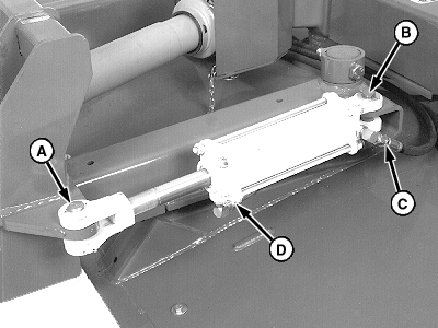
8. Align base end of cylinder with mounting tabs on left-hand hitch arm, as shown. Insert 25 x 112 mm pin (B) through base end of cylinder and tabs. 9. Install one 1-1/32 x 1-3/4 x 0.105 in. washer on each end of pin. Retain with two 4 x 40 mm cotter pins. 10. Align rod end with mounting tab on hitch. Install existing headed pin and cotter pin (A). 11. Connect hydraulic hoses (C and D). 12. Route coupler end of hoses around hitch arm, under driveline, toward right-hand side of machine.
|
|
AG,OUMX005,827 -19-09JUL99-4/5 |
|
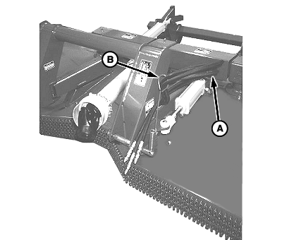
13. Insert all hydraulic hoses through hose holder (B). 14. Install a tie strap around all hoses at approximate location (A).
|
|
AG,OUMX005,827 -19-09JUL99-5/5 |
