Attaching Loader1. Center tractor between loader masts, stopping tractor when hooks (B) on mounting frames are positioned under pins (A) on loader masts on each side.2. Engage parking brake and shut off engine.
|
|
OUMX005,0001504 -19-24JUN02-1/13 |
|
If an accident occurs, see a doctor immediately. Any fluid injected into the skin must be surgically removed within a few hours or gangrene may result. Doctors unfamiliar with this type of injury should reference a knowledgeable medical source. Such information is available from Deere & Company Medical Department in Moline, Illinois, U.S.A. 3. Move loader control lever(s) back and forth and side-to-side (if applicable) several times. (See your tractor Operator's Manual.) Electrohydraulic valve/third function (attachment, such as grapple); a. Turn key to ON position. Do not start tractor engine. b. Press switch on multi-function control lever several times. c. Turn key to OFF position. E-ICV or E-SCV; a. Turn key to ON position. Do not start tractor engine. b. Release interlock. c. Move loader control lever back and forth and side-to-side (if applicable) several times. d. Turn key to OFF position. |
|
 CAUTION:
Escaping fluid under pressure can penetrate the skin causing serious injury. Avoid the hazard by relieving pressure before disconnecting hydraulic or other lines. Tighten all connections before applying pressure. Search for leaks with a piece of cardboard. Protect hands and body from high pressure fluids.
CAUTION:
Escaping fluid under pressure can penetrate the skin causing serious injury. Avoid the hazard by relieving pressure before disconnecting hydraulic or other lines. Tighten all connections before applying pressure. Search for leaks with a piece of cardboard. Protect hands and body from high pressure fluids.
OUMX005,0001504 -19-24JUN02-2/13 |
|
Loader operated with independent control valve on 20, 30, 40, 50 and 55 Series Tractors; Use following special procedure to relieve hydraulic pressure: a. With engine running, move lever forward and to right-hand side. Do not place lever in FLOAT or FAST DUMP positions. b. Hold lever, shut off engine and wait until engine stops before releasing lever. |
|
OUMX005,0001504 -19-24JUN02-3/13 |
|
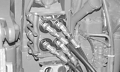
IMPORTANT: Before connecting coupler halves make sure that fittings are free of dirt and debris. Couplers will always connect to a pressurized male tip, providing that the coupler pressure has been released at the valve. To allow oil to flow through coupler, start tractor and operate each function in both directions. NOTE: Hose connections at mid-mount bracket are identified by matching the color-coded cap on the hose end with the same color-coded plug on the mid-mount coupler. (If caps/plugs are missing, see IDENTIFYING HOSE CONNECTIONS in the Service section.) 4. SCV at Rear of Tractor; Connect hydraulics using color-coded dust caps/plugs, identification tags or color-coded tie bands to match mating couplers. |
|
OUMX005,0001504 -19-24JUN02-4/13 |
|
Mid-Mount Couplers; a. Push and hold collar on female coupler. b. Insert hydraulic hose with male end into coupler. c. Release collar on female coupler. d. Repeat for all hydraulic hose connections. |
|
OUMX005,0001504 -19-24JUN02-5/13 |
|
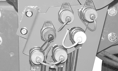
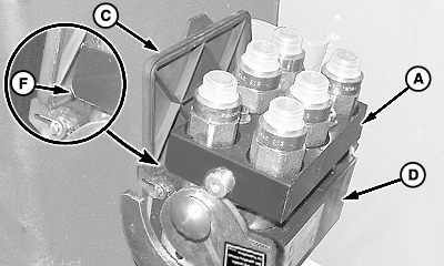
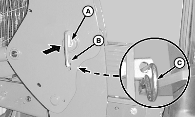
Multi-Coupler; a. Raise cover (A). b. Push red knob (B) IN and rotate lever rearward and down, as shown.
|
|
OUMX005,0001504 -19-24JUN02-6/13 |
|
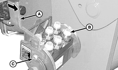
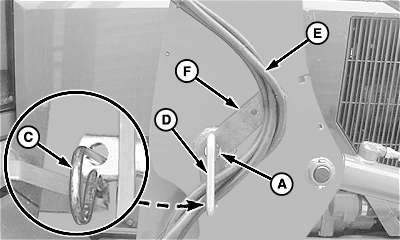
IMPORTANT: Multi-coupler mating halves must align properly or damage to couplers can occur. NOTE: Mobile half of multi-coupler is shown without hydraulic hoses for photographic purposes. c. Place mobile coupler half (A), with chamfered edge (F) toward cover (C), onto stationary coupler. Make sure locating pins (B) on mobile coupler fit into corresponding holes (E) in stationary coupler (D).
|
|
OUMX005,0001504 -19-24JUN02-7/13 |
|
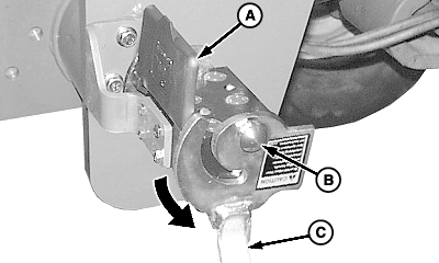
d. Rotate lever (A) to engage pins (C) until a "click" is heard, locking halves together. 5. Start tractor engine. 6. Place transmission in neutral , to allow tractor movement, and release parking brake.
|
|
OUMX005,0001504 -19-24JUN02-8/13 |
|
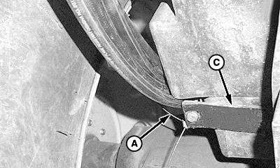
7.
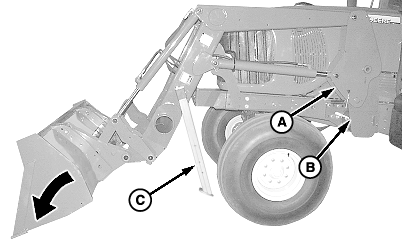
Slowly dump bucket until masts (A) seat in mounting frames (B) on both sides and stands (C) are slightly off ground.
8. Engage parking brake or place transmission in "PARK" and shut off engine.
|
|
OUMX005,0001504 -19-24JUN02-9/13 |
|
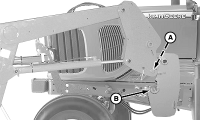
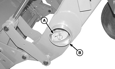
9.
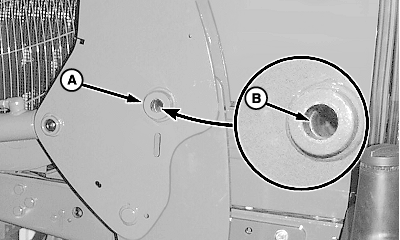
Make sure mast bushings (A) are aligned with frame bushings (B) on both sides of loader.
|
|
OUMX005,0001504 -19-24JUN02-10/13 |
10.
On both sides of loader install pins (A):
|
|
OUMX005,0001504 -19-24JUN02-11/13 |
|
11.
Remove quick lock pins and parking stands/boom service locks.
12. Store parking stands/boom service locks (A) in tube (B). Fasten with quick lock pins.
|
|
OUMX005,0001504 -19-24JUN02-12/13 |
|
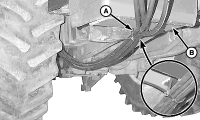
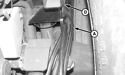
13.
Tractors with hoses routed to rear;
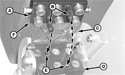
Attach removable tie bands with hoses (A) to underside of tractor at locations (B-D), as shown.
14. Check loader operation.
|
|
OUMX005,0001504 -19-24JUN02-13/13 |