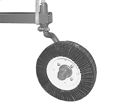
Install Axle Support(s), Spindle(s) and Tailwheel(s)-MX7NOTE: If machine is equipped with two tailwheel supports, perform the following procedures on BOTH tailwheel supports unless noted otherwise. 1. Wrap a lifting strap around axle support tube and attach to a hoist. |
AG,OUO1078,382 -19-09FEB00-1/6 |
|
2.
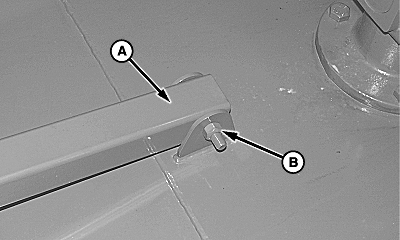
Single Tailwheel;
a. Insert end of axle support tube (A) between mounting flanges located at top, rear of cutter. b. Align holes in tube with holes in mounting flanges and install M16 x 110 cap screw and lock nut (B). Leave lock nut loose.
|
|
AG,OUO1078,382 -19-09FEB00-2/6 |
|
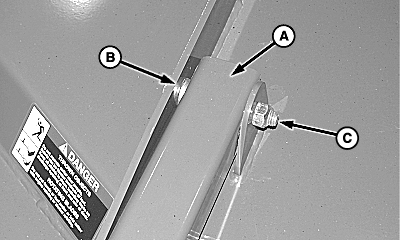
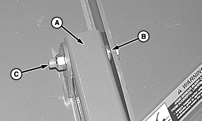
Dual Tailwheel; a. Insert end of axle support tube (A) between mounting flanges located at top, rear of cutter. b. Align holes in tube with holes in mounting flanges and install three 17 x 30 x 3 mm washers (B) at location shown, and M16 x 110 cap screw and lock nut (C). Leave lock nut loose.
|
|
AG,OUO1078,382 -19-09FEB00-3/6 |
|
3.
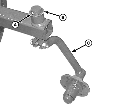
Apply multipurpose grease to pivoting surface of spindle (C).
4. Install spindle (C), one 1-33/64 x 2-1/4 x 0.075 in. washer (B) and 8 x 50 mm spring pin (A).
|
|
AG,OUO1078,382 -19-09FEB00-4/6 |
|
5.
Install tailwheel with four 1/2 x 1-1/2 in. round head bolts and lock nuts. Install lock nuts opposite side of spindle hub. Tighten lock nuts to specifications.
Specification
|
|
AG,OUO1078,382 -19-09FEB00-5/6 |
|
|
|
|
|
|
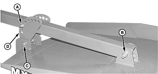
NOTE: Straps are installed in location shown for initial setup. Reposition straps according to desired cutting height. (See ADJUSTING CUTTING HEIGHT/TAILWHEEL POSITION in Operating the Cutter section.) 6. Install two straps (D), as shown, using two M16 x 45 flange head cap screws and lock nuts (C) and one M16 x 110 cap screw and lock nut (A). |
7. Tighten cap screw and lock nut (B). 8. Lower tailwheel and remove lifting strap. |
AG,OUO1078,382 -19-09FEB00-6/6 |
