Detaching Loader
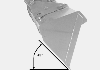
1. Remove toolbox (if equipped). 2. Remove ballast box, if equipped. (See procedure in this section.) 3. Start tractor engine. 4. Dump bucket approximately 45° below level. (Full dump position for self-level loader.) 5. Lower bucket to ground, applying slight down pressure. Do not raise tires off ground. 6. Engage tractor parking brake and/or place transmission in PARK . 7. Shut off tractor engine and remove key. |
|
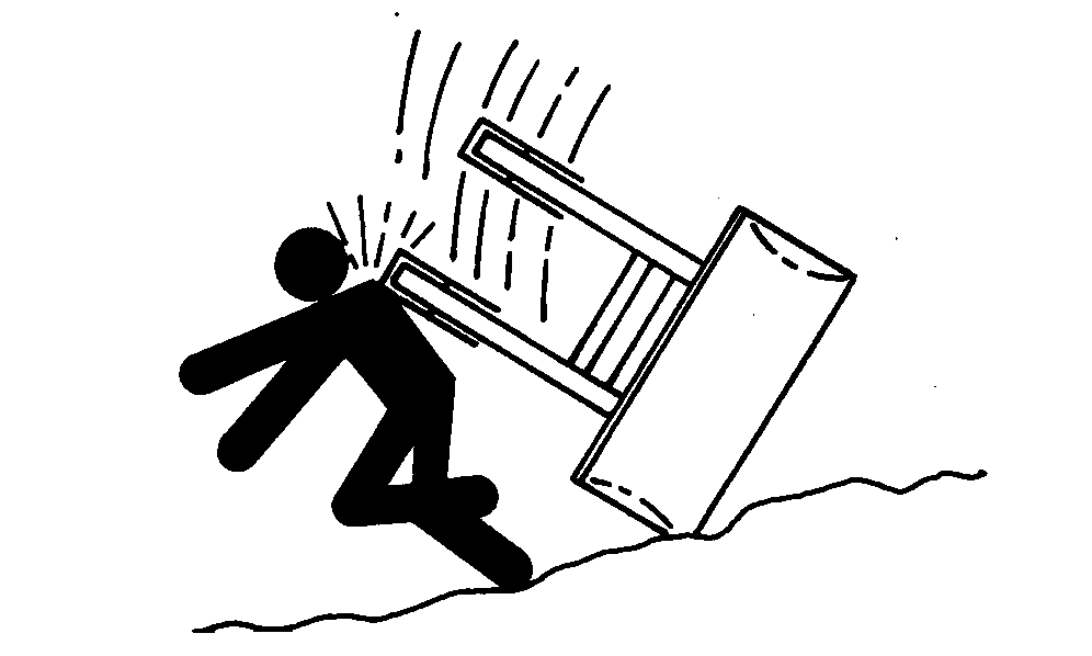
 CAUTION:
To help prevent personal injury caused by a falling loader, always detach on a hard, level surface. Loader must be equipped with a bucket and parking stands.
CAUTION:
To help prevent personal injury caused by a falling loader, always detach on a hard, level surface. Loader must be equipped with a bucket and parking stands.
OUO6077,0001886 -19-06JUN07-1/9 |
|
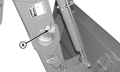
NOTE: 542 parking stands are square and 522 stands are round. Parking procedure is the same. 542 stands shown. Use boards under stands to prevent loader from sinking in soft ground. 8. Remove spring pin (A) from base of stand on right-hand side of loader. 9. Remove stand from tube and replace spring pin in tab at tube. 10. Install stand into bracket as illustrated. Fasten with pin (B) and spring pin. 11. Repeat above steps for stand on left-hand side.
|
|
OUO6077,0001886 -19-06JUN07-2/9 |
|
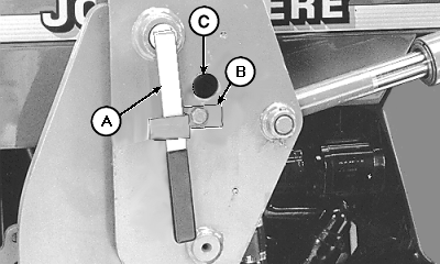
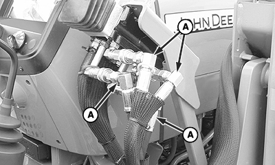
12.
All EXCEPT Single Lever with ICV (Option for 522 only):
Remove spring pin (A) to disconnect hoses from mast.
|
|

OUO6077,0001886 -19-06JUN07-3/9 |
|
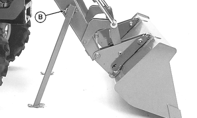
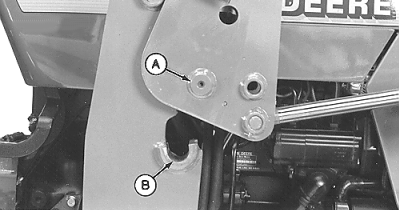
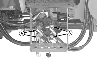
13.
Release pins (A) from clips (B) and remove from both mounting frames. Store pins in holes (C).
|
|
OUO6077,0001886 -19-06JUN07-4/9 |
|
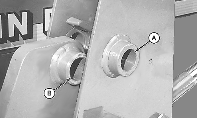
14.
Start tractor engine.
15. Release parking brake and/or place transmission in NEUTRAL . 16. Extend lift cylinders until pocket behind bushing (A) is ahead of bushing (B). NOTE: Parking stands should not contact ground during this operation. Dump bucket if more clearance of stand to ground is required.
|
|
OUO6077,0001886 -19-06JUN07-5/9 |
|
NOTE: Move tractor forward IF necessary to keep hoses loose. 17. Roll back bucket until stands contact ground. Continue to roll back bucket until loader pins (A) lift approximately 152 mm (6 in.) out of frame saddles (B). 18. Engage tractor parking brake and/or place transmission in PARK . 19. Shut off tractor engine and remove key.
|
|
OUO6077,0001886 -19-06JUN07-6/9 |
|
20. Move control lever(s) back and forth and side-to-side (if applicable) several times to relieve hydraulic pressure. (See your tractor Operator's Manual.) |
|
OUO6077,0001886 -19-06JUN07-7/9 |
|
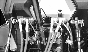
21.
Mid-Mount Couplers:
Disconnect hoses (A) from valve.
|
|
OUO6077,0001886 -19-06JUN07-8/9 |
|
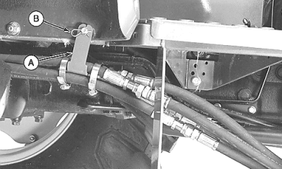
Rear Couplers: a. Remove spring pin (B) and bracket (A) from platform. b. Disconnect hydraulic hoses in back of tractor. 22. Cap and plug hoses and couplers. 23. Store hoses on loader. DO NOT lay them on the ground. 24. Start tractor engine. 25. Disengage tractor parking brake and place transmission in REVERSE . Slowly move away from loader.
|
|
OUO6077,0001886 -19-06JUN07-9/9 |