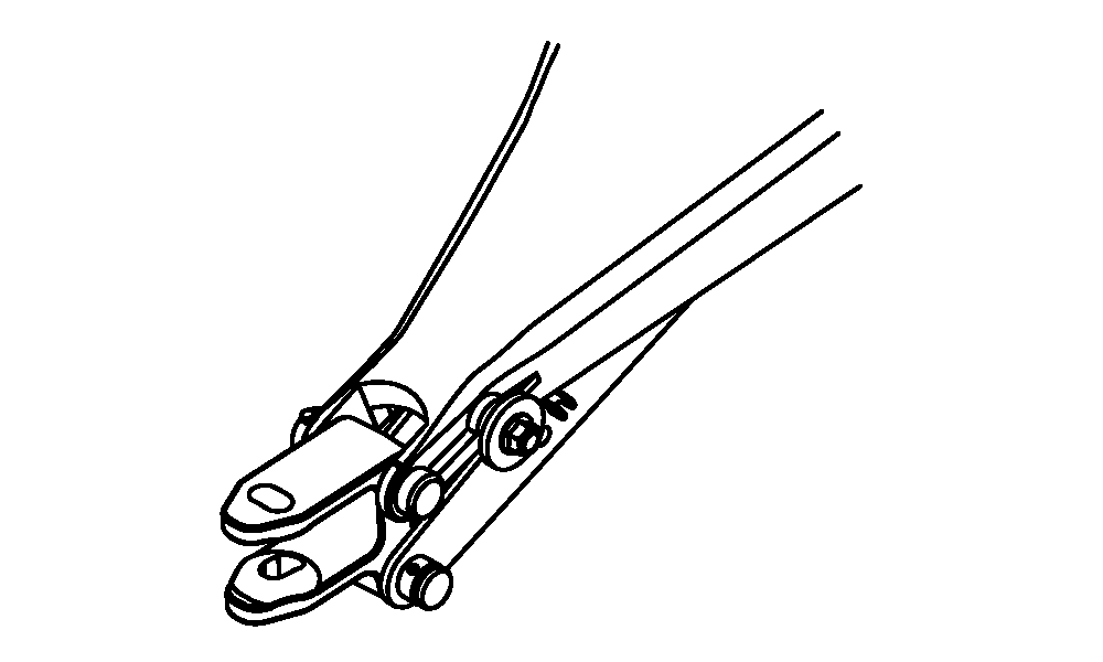
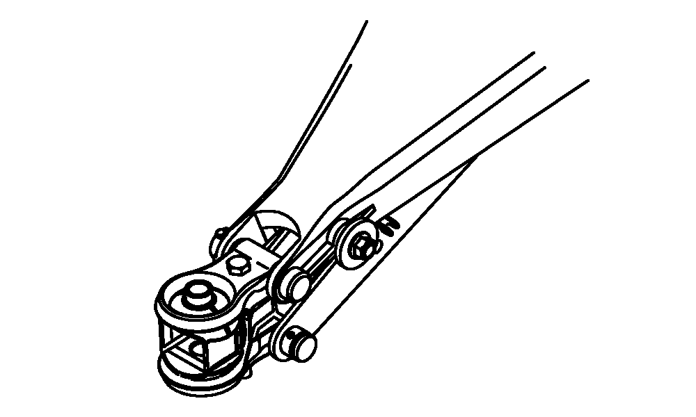
Attaching Rotary Cutter to Tractor DrawbarNOTE: Hitch types are different for each model:
1. Adjust tractor drawbar. (See procedures in Preparing the Tractor section.) 2. Remove hitch pin from tractor drawbar and rotary cutter hitch, if equipped. 3. Back up tractor to rotary cutter. Align tractor drawbar directly in front of rotary cutter hitch. 4. Engage tractor parking brake and/or place transmission in PARK . 5. Shut off tractor engine and remove key. 6. Connect rotary cutter hydraulic hoses to tractor. (See ATTACHING TO TRACTOR HYDRAULIC SYSTEM in this section.) |
|
OUO6077,0001448 -19-26JUN06-1/6 |
|
7.
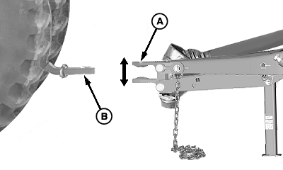
Start engine and extend or retract lift cylinder to raise or lower rotary cutter hitch clevis (A) to match height of drawbar (B).
|
|
OUO6077,0001448 -19-26JUN06-2/6 |
|
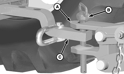
IMPORTANT: Recommended hitch pin size is 28 mm (1-1/8 in.) diameter and at least 178 mm (7 in.) between pin shoulder and spring locking pin hole. 8. Clevis Hitch: a. Back drawbar (C) into clevis (A) until holes in drawbar and clevis align. b. Engage tractor parking brake and/or place transmission in PARK and shut off engine. c. Install hitch pin (B). |
|
OUO6077,0001448 -19-26JUN06-3/6 |
|
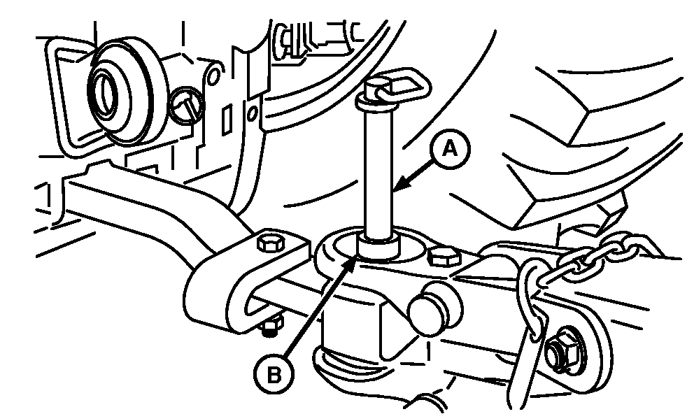
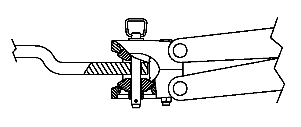
Ball-Type Hitch: a. Back drawbar into ball clevis as far as possible. b. Engage tractor parking brake and/or place transmission in PARK and shut off engine. c. Stand hitch pin (A) in hole of ball (B). d. Start tractor engine and slowly move tractor forward until hitch pin falls through ball and drawbar. 9. Raise rotary cutter to full height. 10. Engage tractor parking brake and/or place transmission in PARK and shut off engine.
|
|
OUO6077,0001448 -19-26JUN06-4/6 |
|
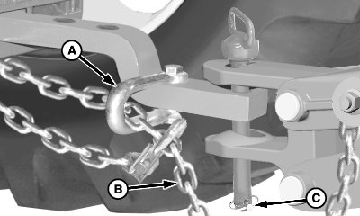
IMPORTANT: Ensure hitch pin is through clevis and drawbar. 11. Install quick lock pin (C). IMPORTANT: To avoid breaking chain (B), adjust chain to remove all slack except what is needed for turns. 12. Route safety chain (B) through intermediate safety chain support (A) and connect to tractor drawbar supporting structure. Do not fasten to drawbar. Provide only enough slack in chain to permit turning. |
|
OUO6077,0001448 -19-26JUN06-5/6 |
|
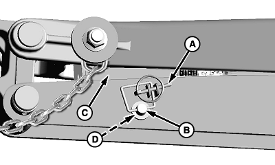
13.
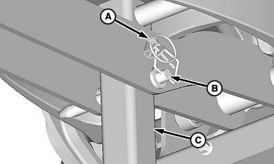
Remove quick-lock pin (A) and pin (B).
14. Fold parking stand (C) up into storage position and install pin (B) in hole (D). Install quick lock pin (A) as shown.
|
|
OUO6077,0001448 -19-26JUN06-6/6 |
