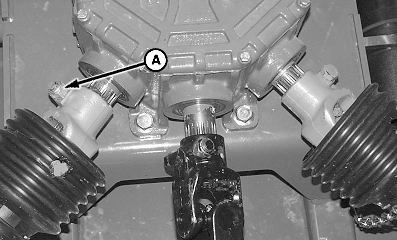
Removing and Installing Wing Drivelines1. Remove quick-lock pins and raise splitter gear case shield and wing gear case shield.2. Remove cap screw and lock nut (A) from driveline at splitter gear case. 3. Remove lock pin (B) from driveline at wing gear case. 4. Remove driveline. 5. Install driveline in reverse order of removal. Tighten hardware to specifications. Driveshaft Hardware - Specification
|
|
OUO6077,00014A9 -19-30JUN06-1/1 |

