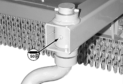
Every 50 HoursSwivel Hitch-If Equipped (Pull-Type) |
|
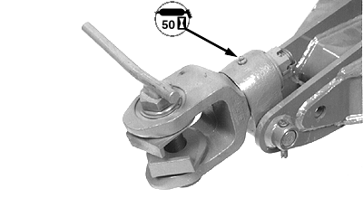
OUO6038,0001A17 -19-19SEP07-1/8 |
|
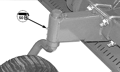
Bellcrank (Pull-Type)
|
|
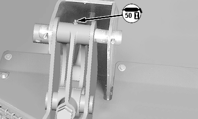
OUO6038,0001A17 -19-19SEP07-2/8 |
|
|
|
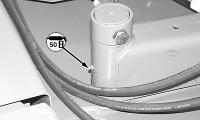
Hitch Arms (Semi-Mount with Hydraulic Offset) (Left and Right-Hand Side)
|
OUO6038,0001A17 -19-19SEP07-3/8 |
|
|
|
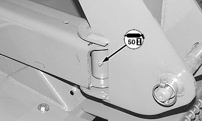
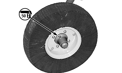
Tailwheel Spindles (Lift-Type and Semi-Mount)
|
OUO6038,0001A17 -19-19SEP07-4/8 |
|
Tailwheel Bearings
|
|
OUO6038,0001A17 -19-19SEP07-5/8 |
|
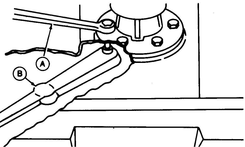
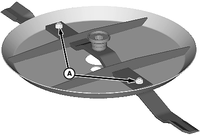
Tightening Gear Case Mounting Hardware
Before servicing machine refer to LUBRICATING AND MAINTAINING MACHINE SAFELY at the beginning of this section. IMPORTANT: To help prevent structural damage caused by loose hardware, tighten gear case hardware as specified. Check torque after first 8 hours of use and every 50 hours thereafter. NOTE: Use an assistant to aid in tightening procedure. Access holes are provided in bottom of blade holder pan. Manually rotate blade holder to align holes with gear case mounting hardware. Tighten gear case mounting hardware to specifications using a wrench (A), torque wrench (B) and a torque multiplier if necessary. Specification
|
|
OUO6038,0001A17 -19-19SEP07-6/8 |
|
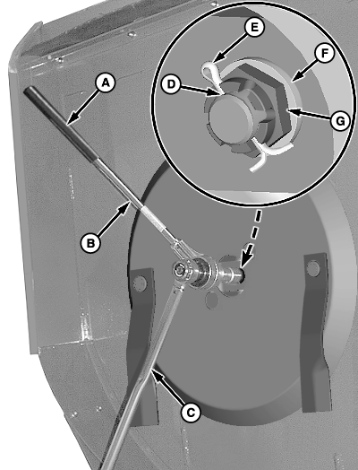
Tightening Blade Holder Hardware
Before servicing machine refer to LUBRICATING AND MAINTAINING MACHINE SAFELY at the beginning of this section. IMPORTANT: Operating with a loose blade holder can cause damage to the splined connection. To ensure proper seating between the blade holder and output shaft, two initial tightenings are required. Retighten after one hour and again after the first day of operation. In severe cutting conditions, recheck torque every 50 hours. 1. Remove and discard existing cotter pin.2. Make sure washer (F) and M30 nut (G) are installed as shown. Tighten nut to specification using a torque wrench (C), torque multiplier (B) and a long piece of pipe (A). Position pipe into a corner of the machine. Specification
NOTE: Make sure slots in nut (G) are aligned with hole (D) in shaft after tightening to specified torque. If necessary, tighten nut slightly more to align slots with hole. 3. Install NEW cotter pin (E). |
|
OUO6038,0001A17 -19-19SEP07-7/8 |
|
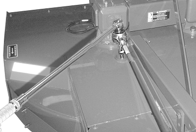
Check Blade Hardware Torque
Manually rotate driveline to align each lock nut (A) with access hole in top of deck. Position torque multiplier, as shown. Tighten lock nuts (A) according to specification. Specification
|
|
 CAUTION:
Before servicing machine refer to LUBRICATING AND MAINTAINING MACHINE SAFELY at the beginning of this section.
CAUTION:
Before servicing machine refer to LUBRICATING AND MAINTAINING MACHINE SAFELY at the beginning of this section.
OUO6038,0001A17 -19-19SEP07-8/8 |