Detach Loader
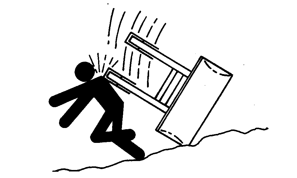
 CAUTION:
W14000-UN-05OCT88
W08535-UN-26MAR07
-
Start tractor engine.
-
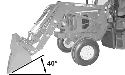
Dump bucket approximately 40° below level.
-
Lower bucket to ground. Apply slight downward pressure. Do not raise tires off ground.
-
Engage parking brake or place transmission in PARK and shut off engine.
-
W20526-UN-29SEP095000 Series Tractors
W20529-UN-29SEP095065M, 5075M, 5085M, 5095M, and 5105M Tractors
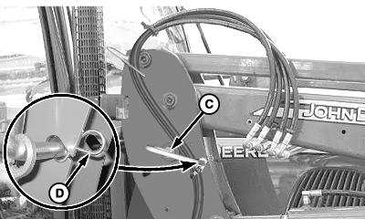
W20528-UN-13OCT095070M, 5080M, 5090M, and 5100M Tractors
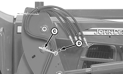
W20527-UN-12OCT096D, 6000, 6003, and 7000 Series Tractors
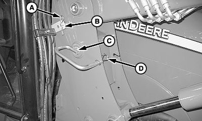
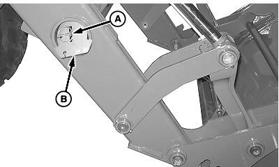
A - Spring Locking Pin
B - Hose Holder
C - Mast Pin (1 each side)
D - Spring Locking Pin (1 each side)
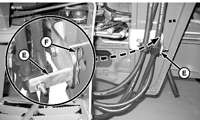
E - Bottom Hose Holder
F - Spring Locking Pin
5000 Series Tractors: Remove spring locking pin (A) and holder (B). Replace spring locking pin on mast. -
5065M, 5075M, 5085M, 5095M, and 5105M Tractors: Remove spring locking pin (F) and bottom holder (E). Replace spring locking pin on holder.
-
NOTE: Roll bucket back and forth, if necessary, to loosen mast pins (C).
All tractors: Remove spring locking pins (D) and mast pins (C) from both sides. Replace spring locking pins on mast pins.
-
W20520-UN-30SEP09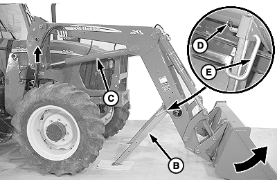
W20530-UN-30SEP09A - Quick Lock Pin (1 each side)
B - Parking Stand (1 each side)
C - Cylinder, Lift (1 each side)
D - Spring Locking Pin (1 each side)
E - Mast Pin (1 each side)
Remove quick-lock pin (A) and parking stand (B) from both sides of storage tube. Replace quick-lock pins. -
Install parking stands with base of stands parallel to ground. Fasten to boom using mast pins (A) and spring locking pins (B) as shown. Place boards under stands if parked on soft ground.
-
Start tractor engine. Place transmission in NEUTRAL, to allow tractor movement, and release parking brake.
-
Extend lift cylinders (C) until masts move forward.
-
Slowly roll back bucket until stands contact ground and loader lifts out of mounting frames. Drive ahead, as necessary, to keep hoses slack.
-
 CAUTION:
X9811-UN-23AUG88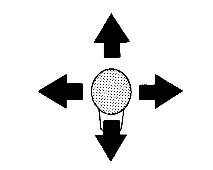
W03317-UN-31MAR99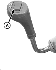
W08200-UN-22SEP06Control Lever—Early Version
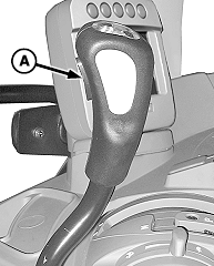
W08201-UN-22SEP06Control Lever—Later Version
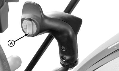
W09661-UN-17JUL08Control Lever—5025, 5M Series, and 6D Series Tractors
A - Switch
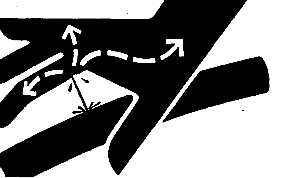
Escaping fluid under pressure can penetrate the skin causing serious injury. Avoid the hazard by relieving pressure before disconnecting hydraulic or other lines. Tighten all connections before applying pressure. Search for leaks with a piece of cardboard. Protect hands and body from high-pressure fluids.If an accident occurs, see a doctor immediately to surgically remove any fluid injected into the skin. Fluid must be removed within a few hours to avoid gangrene. Doctors unfamiliar with this type of injury should reference a knowledgeable medical source. Such information is available from Deere & Company Medical Department in Moline, Illinois, U.S.A.
Shut off engine. Turn key to ON position. Do not start tractor engine. Move loader control lever in all directions several times. (See your tractor Operator's Manual for specific procedures about relieving hydraulic pressure.)
-
If equipped with a mechanical lever and electro-hydraulic valve on third function (attachment, such as grapple): Press switch (A) several times.
-
Turn key to OFF position.
-
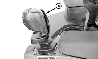
W08193-UN-20SEP06A - Interlock Switch Actuator
If equipped with Electronic Control Lever (E-ICV): Release interlock. Operator’s hand must be inserted to hold switch actuator (A) open. -
Move loader control lever back and forth and side-to-side several times.
-
Turn key to OFF position.
-
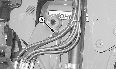
W08096-UN-01SEP06Right-Hand Side
A - Connector (if equipped)
If equipped with Global Cylinder Latching System: Detach harness connector (A). -
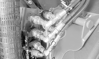
W08003-UN-10JUN086000 and 7000 Series Shown
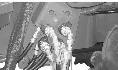
W21247-UN-02DEC105E Series Tractors (Two-Function Shown)
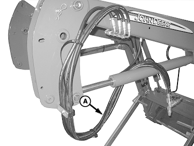
W09531-UN-28AUG08A - Hoses
If equipped with mid-mount couplers: Perform the following:-
Push and hold collar on female coupler.
-
Disconnect coupler.
-
Release collar on female coupler.
-
Install dust caps on couplers.
-
Repeat for all hydraulic hose connections.
-
Place hoses (A) on lift cylinder as shown. Do not place hoses on ground.
-
-
IMPORTANT:
W09815-UN-02SEP08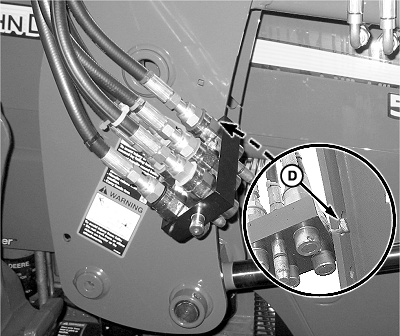
W09816-UN-27AUG08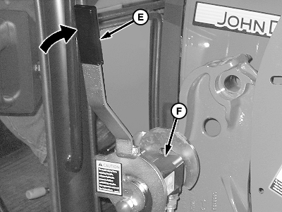
W20545-UN-12OCT09A - Red Knob
B - Pin (1 each side)
C - Loader Coupler Half with Hoses
D - Storage Hole
E - Lever
F - Cover
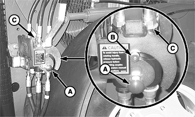
Avoid seal damage. Relieve hydraulic pressure before multicoupler disconnection. (See your tractor Operator's Manual.)If equipped with Multicoupler: Perform the following:
-
Push red knob (A) IN and rotate lever rearward to disengage pins (B) and coupler halves.
-
Remove loader coupler half (C) from tractor coupler and insert pin into storage hole (D) on mast. Do not place hoses on ground.
-
IMPORTANT: Avoid damage from contact with tractor fender or wheel. Lever (E) must be in the locked (UP) position. Cover (F) must also be lowered to protect connections.
Rotate lever (E) forward until locked in the UP position.
-
Lower cover (F).
-
-
Place transmission in REVERSE and back tractor slowly away from loader.
|
OUO6064,0000B7E-19-20130607 |


