Detach the Bucket or Attachment
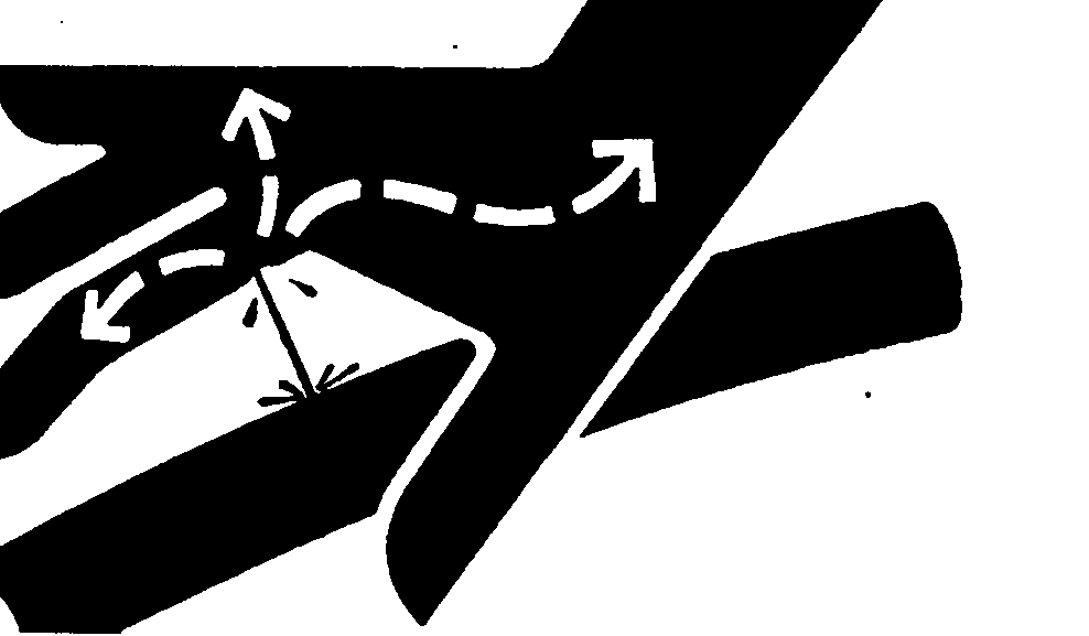
 CAUTION: Escaping fluid under pressure can penetrate the skin causing serious injury. Avoid the hazard by relieving pressure before disconnecting hydraulic or other lines. Tighten all connections before applying pressure. Search for leaks with a piece of cardboard. Protect hands and body from high-pressure fluids.
If an accident occurs, see a doctor immediately to surgically remove any fluid injected into the skin. Fluid must be removed within a few hours to avoid gangrene. Doctors unfamiliar with this type of injury should reference a knowledgeable medical source. Such information is available from Deere & Company Medical Department in Moline, Illinois, U.S.A.
X9811-UN-23AUG88
W08200-UN-22SEP06
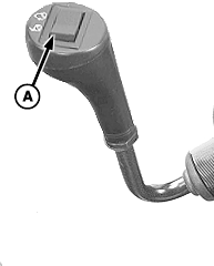
Mechanical EH—Early Version
W08201-UN-22SEP06
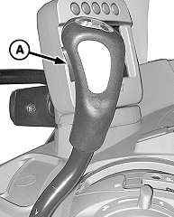
Mechanical EH—Later Version
W08202-UN-22SEP06
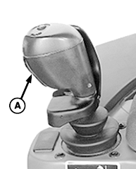
Electronic
W09539-UN-06JUN08
5025, 5M Series, and 6D Series Tractors
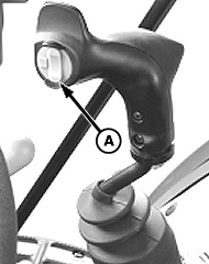
A - Switch
If equipped with hydraulic operated attachment (such as a grapple): Disconnect hydraulic hoses as follows:Turn key to ON position. Do not start tractor engine.
Press switch (A) on multi-function control lever several times.
Turn key to OFF position.
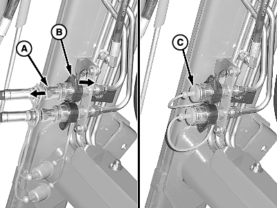
W08031-UN-15AUG06A - Coupler (Male)
B - Collar
C - Plug
If equipped with Attachment Quick Couplers:Push and hold collar (B) on female coupler.
Disconnect male coupler (A).
Release collar on female coupler.
Place cap on male tip at hose end and insert plug (C) into female coupler.
Repeat for remaining hydraulic hose connection.
W09851-UN-03SEP08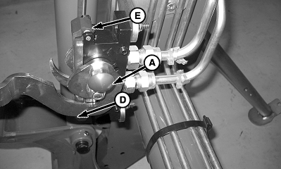
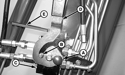
W09852-UN-03SEP08A - Knob
B - Pin (1 each side)
C - Attachment Coupler Half with Hoses
D - Lever
E - Cover
If equipped with Attachment Multicoupler:Push red knob (A) IN and rotate lever (D) forward to disengage pins (B) and separate coupler halves.
Remove attachment coupler half with hoses (C) from loader coupler.
IMPORTANT: Avoid interference with tractor components. Lever (D) must be in the locked (UP) position when coupler half with hoses is removed. Cover (E) must also be lowered to protect connection surface of loader coupler half.
Lower cover (E).
Rotate lever rearward until it is locked in the UP position.
500-Style Carrier Attachment
W09889-UN-12SEP08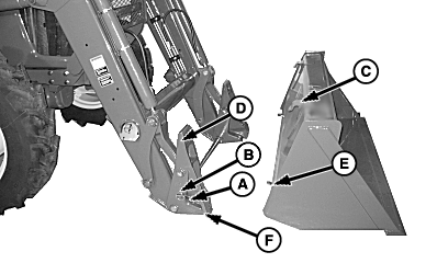
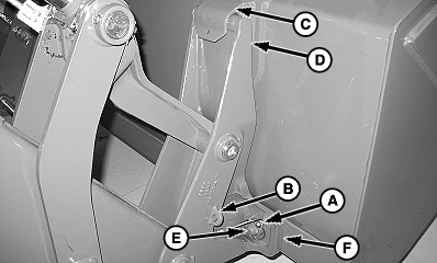
W09890-UN-12SEP08A - Pin, Quick Lock
B - Storage Position
C - Hook
D - Carrier
E - Pin, Bucket
F - Strap
Start tractor engine.NOTE: Procedure is the same for all attachments. Bucket attachment shown.
Roll bucket back slightly and raise boom approximately 460 mm (18 in.) above ground level.
Set parking brake and/or place transmission in PARK and shut off tractor engine.
Remove quick lock pin (A) from each side of attachment.
Store pins in storage position (B).
Start tractor engine. Slowly extend bucket cylinders until pin (E) releases from carrier strap (F) on each side of bucket/attachment.
Lower loader boom, place transmission in REVERSE and move away from bucket/attachment. Carrier (D) will release from hook (C) on each side of bucket/attachment.
Set parking brake and/or place transmission in PARK. Shut off tractor engine and remove key.
600-Style Carrier Attachment with QUIK-CHANGE™ Latch Plates
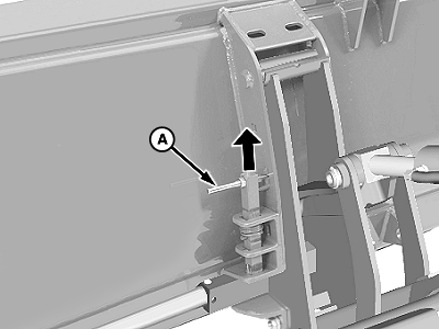
W08033-UN-22AUG06Right-Hand Side Shown
A - Pin (1 each side)
Level the attachment and lower until approximately 400 mm (16 in.) off ground.Place transmission in PARK and shut off engine.
At each side of bucket or attachment: Lift pins (A) and pull toward outside to lock in raised position.
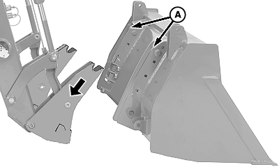
W08034-UN-17AUG06A - Pins
Start tractor engine and slowly extend bucket cylinders until holder clears pockets.Lower loader to clear pins (A).
Lower loader to ground and turn off tractor engine.
Global Carrier Attachment (Manual)
W09662-UN-21JUL08Left-Hand Side
W08080-UN-25AUG06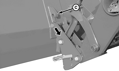
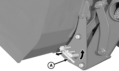
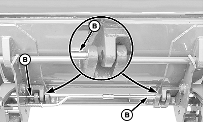
W09663-UN-21JUL08A - Latch Lever
B - Pins
C - Hook (1 each side)
Level bucket or attachment and lower until approximately 400 mm (16 in.) off ground.Roll back bucket or attachment slightly to allow movement of latch pin.
Place transmission in PARK and shut off engine.
Pull latch lever (A) outward, to disengage carrier pins (B) from bucket, and rotate upward to lock into place.
Start tractor engine. Place transmission in NEUTRAL and release parking brake.
Tilt carrier forward (extend bucket cylinders) and lower loader until carrier brackets clear hooks (C).
NOTE: If not installing additional attachment, rotate carrier all the way back to engage pins.
Lower loader to ground and turn off tractor engine.
Skid-Steer Carrier Attachment
W08389-UN-29NOV06Left-Hand Lock Pin
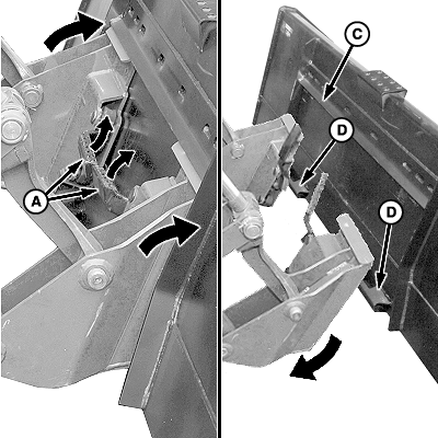
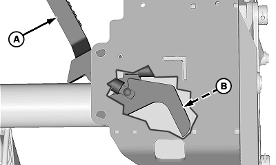
W08399-UN-28NOV06A - Latch Handles
B - Lock Pin (1 each side)
C - Lip
D - Latches
Start tractor engine and position machine on flat level ground. Level bucket or attachment and lower loader completely to the ground.Place transmission in PARK and shut off engine.
IMPORTANT: Make sure both latch handles (A) are up and lock pins (B) are fully retracted.
Raise both latch handles (A) to the UP (unlatched) position.
Start tractor engine and place transmission in NEUTRAL. Slowly tilt carrier forward (extend bucket cylinders) until carrier clears bottom latches (D).
Place transmission in REVERSE and slowly back away from bucket or attachment.
Lower loader to the ground, place transmission in PARK, shut off engine and remove key.
OUO6077,0001803-19-20091012 |


