Detach Loader (If Equipped with Optional Parking Stands)
Remove Ballast Box
-
 CAUTION: To prevent personal injury from tractor instability,
remove ballast box from hitch before detaching loader.
CAUTION: To prevent personal injury from tractor instability,
remove ballast box from hitch before detaching loader.To prevent personal injury caused by unexpected movement:
- Park machine on a level surface.
- Engage tractor parking brake and/or place transmission in PARK.
- Disengage PTO.
- Shut off tractor engine and remove key.
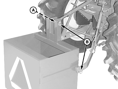
W05958-UN-27MAR03A - Center Link
B - Quick-Lock Pins (3 used)
Ballast Box with Three-Point Hitch:-
Slowly push hitch control lever to lower ballast box to the ground.
-
Remove quick-lock pins (B) from hitch pins and install in storage position on tractor draft links.
-
Remove tractor draft links from ballast box hitch pins.
-
Remove quick-lock pin (B) from center link (A). Position tractor center link in transport location. Reinstall center link pin/hardware.
-
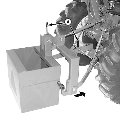
W05201-UN-06MAR02A - Latch Control Levers
Ballast Box with Quick-Coupler:-
Slowly push hitch control lever to lower ballast box close to the ground.
-
Raise both latch control levers (A) on quick coupler.
-
Start tractor engine.
-
Lower ballast box to the ground. Continue lowering quick-coupler until hooks clear ballast box hitch pins.
-
-
Carefully drive tractor away.
Detach Loader
-
 CAUTION: To prevent personal injury from loader instability,
do not attempt to park a loader without the parking kit. Fixed loaders
are permanently attached to the tractor and cannot be detached by
the operator. See your John Deere dealer for a Parking Stand Kit attachment
to convert a fixed loader to a parking loader.
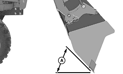
W23354-UN-28JAN13A - Angle, 45°
Raise boom slightly and dump bucket to 45° below level. -
Lower bucket to ground and apply slight pressure. Do not raise front tires off ground.
-
Shut off tractor engine.
-
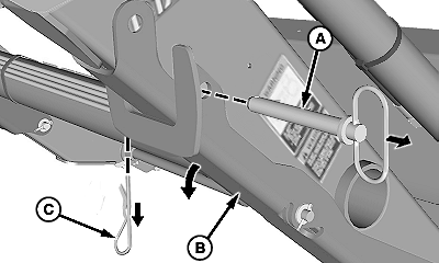
W23358-UN-22JUL13Right-Hand Side Shown
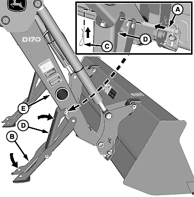
W23359-UN-16MAY13A - Pin (1 each side)
B - Parking Stand (1 each side)
C - Quick-Lock Pin (1 each side)
D - Support Bracket
E - Boom
Lower parking stands on both sides:-
Remove quick-lock pin (C) and pin (A).
-
Lower parking stand (B) and raise support bracket (D) toward boom (E) as shown.
-
Install pin (A) through support bracket and boom. Fasten using quick-lock pin (C) as shown.
-
Repeat Steps a—c on opposite side.
-
-
IMPORTANT:
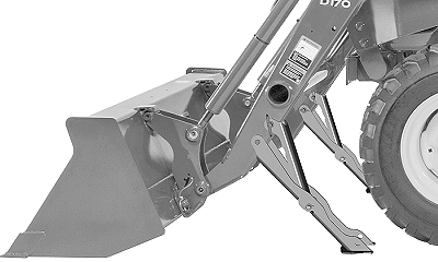
W23852-UN-19JUL13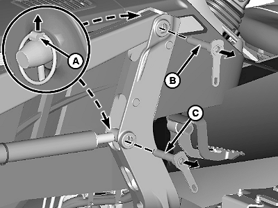
W23360-UN-19JUL13Left-Hand Side Shown
A - Quick-Lock Pin (2 per side)
B - Pivot Pin, Long (1 per side)
C - Pivot Pin, Short (1 per side)
If necessary, move tractor and adjust loader to ensure that bucket and stands are firmly on ground.Lower loader until bucket and parking stands are flat on ground.
-
Move bucket until pressure is removed from pivot pins (B and C). Do not raise parking stands off ground.
-
Shut off tractor engine and remove key.
-
Remove quick-lock pins (A) and pivot pins (B and C).
-
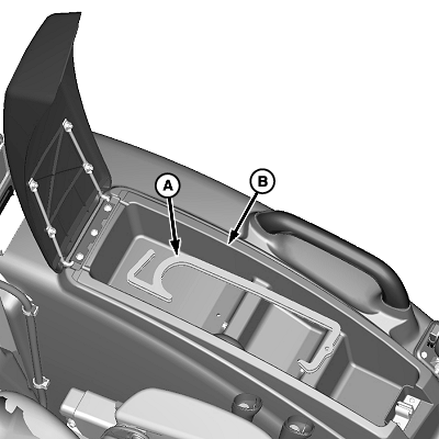
W23357-UN-22JAN13A - Supports (2 used)
B - Storage Compartment
Remove supports (A) from tractor storage compartment (B). -
IMPORTANT:
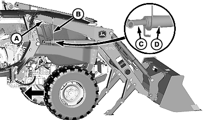
W23363-UN-21MAY13A - Boom (1 each side)
B - Support (1 per side)
C - Rod, Lift Cylinder (1 each side)
D - Housing, Lift Cylinder (1 each side)
Avoid damage to lift cylinder rods (C). DO NOT allow rods to rest in supports (B).Hang supports (B) on booms (A) and place lift cylinder housings (D) in supports as shown.
-
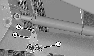
W23361-UN-19JUL13Right-Hand Side Shown
A - Hook (1 each side)
B - Pivot Pin (1 long, 1 short each side)
C - Quick-Lock Pins (2 each side)
Install quick-lock pins (C) on pivot pins (B) and store pivot pins on hooks (A) as shown. -
Start tractor engine.
-
Slowly back tractor away from loader.
-
Turn off tractor engine and remove key.
-
 CAUTION:
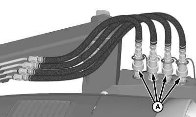
W23619-UN-15MAY13Couplers (Mast-Mounted)
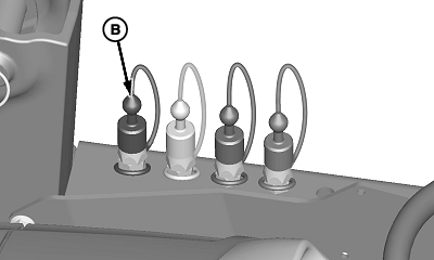
W23620-UN-16MAY13Caps (Mast-Mounted Couplers)
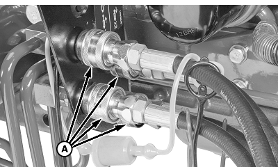
W23760-UN-28MAY13Couplers (Mid-Mount)
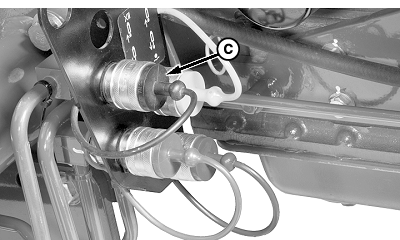
W23761-UN-28MAY13Plugs (Mid-Mount Couplers)
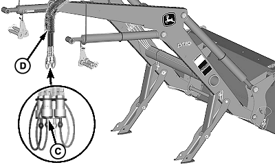
W23362-UN-15JUL13Plugs (Loader Hose Couplers)
A - Couplers
B - Cap (4 used)
C - Plug (4 used)
D - Hoses
To help prevent injury from escaping hydraulic oil under pressure, relieve pressure in the system.Move control lever back and forth and side-to-side (if applicable) several times. (See your tractor Operator’s Manual.)
-
Disconnect hydraulic couplers (A).
-
Install dust caps (B) and plugs (C) on coupler ends as shown.
-
Store loader hoses (D) on boom as shown.
|
OUO6038,0002195-19-20130719 |