Attach Loader (If Equipped with Optional Parking Stands)
-
Attach ballast box to tractor. (See ATTACH BALLAST BOX TO TRACTOR HITCH in Prepare Tractor section.)
-
Start tractor engine.
-
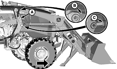
W23364-UN-21MAY13Right-Hand Side Shown
A - Mounting Frame (1 each side)
B - Boom (1 each side)
C - Cylinder (1 each side)
Drive into loader until booms (B) and cylinders (C) are positioned inside mounting frames (A). -
Turn tractor engine off.
-
 CAUTION:
Avoid injury from escaping hydraulic oil under pressure, relieve pressure in the system.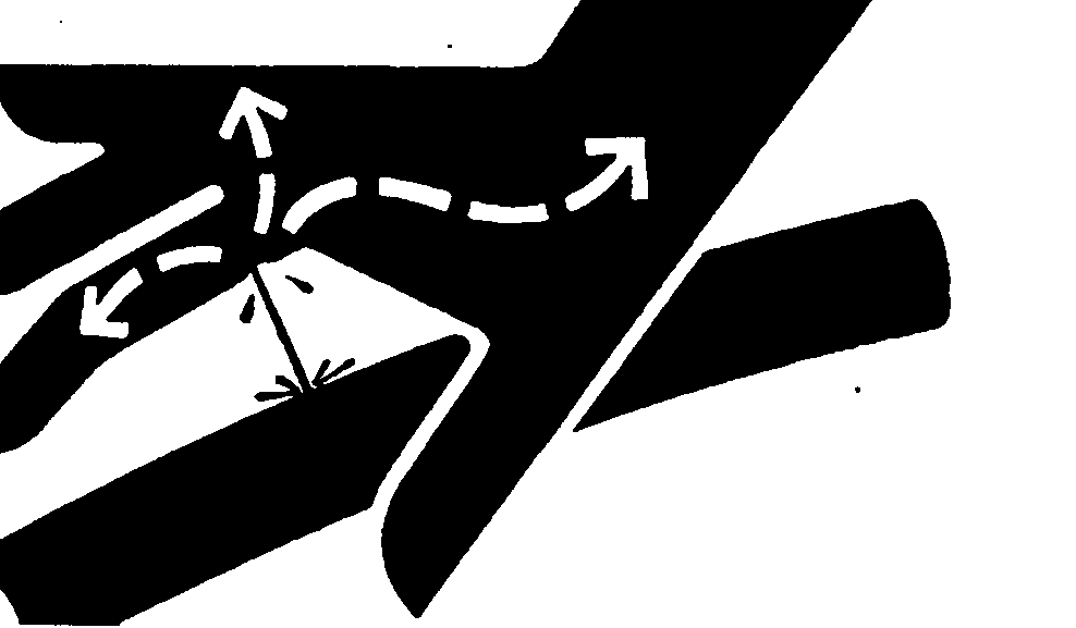
X9811-UN-23AUG88Move control levers back and forth and side-to-side (if applicable) several times to relieve hydraulic system pressure. (See your tractor Operator’s Manual.)
-
 CAUTION:
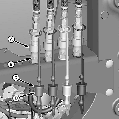
W23752-UN-17MAY13Couplers (Mast-Mounted)
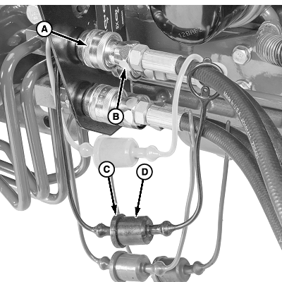
W23759-UN-28MAY13Couplers (Mid-Mount)
A - Coupler, Female (4 used)
B - Coupler, Male (4 used)
C - Plug, Color-Coded (4 used)
D - Cap, Color-Coded (4 used)
Avoid personal injury caused by unexpected loader movement. Hose connections must be correct for loader to respond as expected when control lever is moved.IMPORTANT: Before connecting hoses ensure that couplers are free of dirt and debris.
NOTE: Identify hose connections using color-coded caps and plugs on couplers and hoses.
Connect couplers (A and B).
-
Connect all plugs and caps (C and D) as shown.
-
Start tractor engine.
-
 CAUTION:

W20683-UN-17FEB10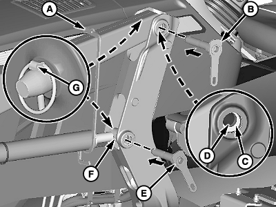
W23365-UN-19JUL13Left-Hand Side Shown
A - Support (1 each side)
B - Pivot Pin, Long (1 each side)
C - Bushing, Mounting Frame (1 each side)
D - Bushing, Boom (1 each side)
E - Pivot Pin, Short (1 each side)
F - Bushing, Lift Cylinder (1 each side)
G - Quick-Lock Pin (2 each side)
Avoid personal injury. Do not insert fingers into holes while aligning components.Pivot bucket to align bushings (C and D).
-
Engage tractor parking brake and place transmission in PARK.
-
Turn tractor engine off and remove key.
-
NOTE: Insert a tapered pin or drift through back of mounting frame to align bushings and install pivot pins.
Install long pivot pin (B) in top hole and fasten using quick-lock pin (G).
-
Move tractor control lever into float position.
-
Remove support (A) and place in tractor storage compartment.
-
Align cylinder bushing (F) with mounting frame bushing.
-
Install short pivot pin (E) and fasten with quick-lock pin (G).
-
Repeat Steps 12—16 on opposite side.
-
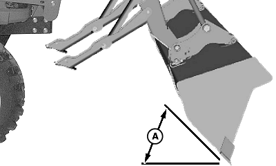
W23366-UN-29JAN13Bucket Position
A - Angle, 45°
Start tractor, raise boom slightly, and dump bucket to 45° below level. -
Lower bucket to ground and apply slight pressure. Do not raise front tires off ground.
-
Shut off tractor and remove key.
-
W23367-UN-16MAY13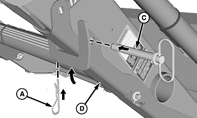
W23368-UN-22JUL13Right-Hand Side Shown
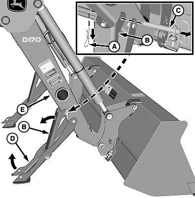
A - Quick-Lock Pin (1 each side)
B - Parking Stand Support (1 each side)
C - Pin (1 each side)
D - Parking Stand (1 each side)
E - Boom (1 each side)
Remove quick-lock pins (A) and pins (C) from parking stands (D). -
Rotate supports (B) outward and raise parking stands (D) to underside of booms (E). Fasten using pins (C) and quick-lock pins (A).
-
Check for proper loader operation in response to control lever. (See OPERATE LOADER WITH MULTI-FUNCTION LEVER in Controls section.)
|
OUO6038,0002196-19-20130719 |