Attach Loader
-
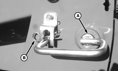
W22802-UN-15AUG12A - Distance, 75 mm (3 in.)
Attach ballast box. (See procedure in Preparing the Tractor section.) -
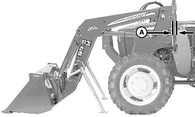
Position tractor between loader masts.
-
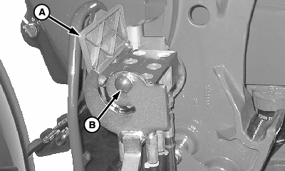
Stop tractor with backs of loader masts approximately 75 mm (3 in.) (A) ahead of fronts of mounting frames (B).
-
Place transmission in PARK and shut off engine.
-
 CAUTION:
Escaping fluid under pressure can penetrate the skin causing serious injury. Avoid the hazard by relieving pressure before disconnecting hydraulic or other lines. Tighten all connections before applying pressure. Search for leaks with a piece of cardboard. Protect hands and body from high pressure fluids.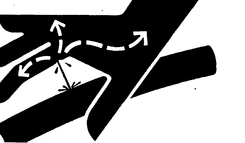
X9811-UN-23AUG88If an accident occurs, see a doctor immediately. Any fluid injected into the skin must be surgically removed within a few hours or gangrene may result. Doctors unfamiliar with this type of injury should reference a knowledgeable medical source. Such information is available from Deere & Company Medical Department in Moline, Illinois, U.S.A.
Move control lever is all directions several times to relieve hydraulic pressure. (See tractor Operator's Manual.)
-
CAUTION:
W09730-UN-22AUG08Single-Lever ICV (Option)
W09731-UN-22AUG08Mid-Mount Valve
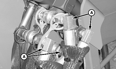
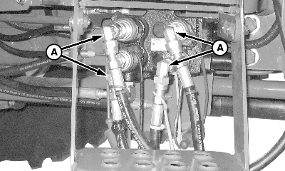
A - Loader Hoses
Help prevent personal injury caused by unexpected loader movement. Anticipated loader movement responds to control lever only if hoses are connected correctly.IMPORTANT: Before connecting hoses, make sure that fittings are free of dirt and debris.
NOTE: Hose connections are identified by matching the color-coded cap on the hose end with the same color-coded plug on the control valve coupler. If caps are missing or not equipped, see IDENTIFYING HOSE CONNECTIONS in Service section for replacements.
Attach Mid-Mount Couplers (if equipped): Connect hoses (A) using color-coded dust caps to match hoses to couplers.
-
W21206-UN-13DEC10A - Cover
B - Knob
Connect Multicoupler (5M Series and 5105ML tractors, if equipped):-
Raise cover (A).
-
Push in red knob (B) and rotate lever rearward and down, as shown.
-
IMPORTANT:
Multicoupler mating halves must align properly or damage to couplers can occur.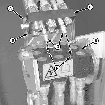
W24712-UN-17FEB14Place loader coupler half (C), with chamfered edge (B) toward cover (A), onto tractor coupler (E). Make sure locating pins (D) on loader coupler fit into corresponding holes (F) in tractor coupler (E).
-
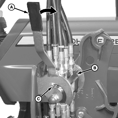
W21207-UN-13DEC10A - Lever
B - Coupler, Loader Half
C - Pin (1 each side)
Rotate lever (A) to engage pins (C) on loader coupler half (B) locking halves together.
-
-
Place transmission in NEUTRAL to allow tractor movement.
-
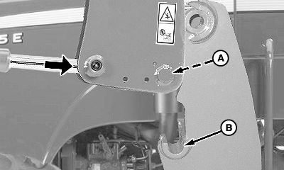
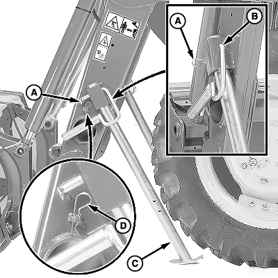
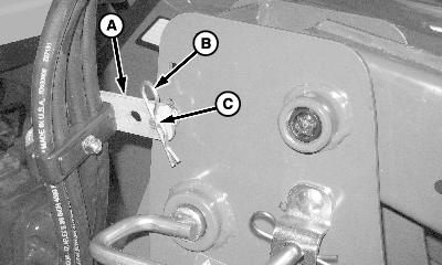
W22803-UN-08AUG12A - Pin (1 each side)
B - Saddle (1 each side)
Extend lift cylinders until pins (A) of masts contact front of frame directly above saddles (B). -
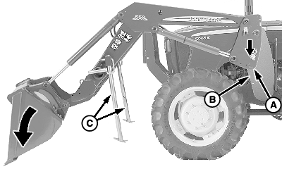
W22804-UN-08AUG12A - Mast
B - Mounting Frame
C - Parking Stands
Dump bucket until masts (A) seat in mounting frames (B) on both sides, and stands (C) are slightly off ground as shown. -
Place transmission in PARK and shut off engine.
-
W22805-UN-23JUL12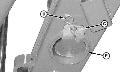
W09737-UN-04SEP08A - Spring Locking Pin (1 each side)
B - Mast Pin (1 each side)
C - Parking Stand (2 used)
D - Spring Locking Pin (1 each side)
E - Storage Tube
Remove spring locking pins (A), mast pins (B) and parking stands (C). -
Remove spring locking pins (D) from storage location.
-
Install parking stands (C) into each end of storage tube (E). Fasten with spring locking pins (D).
-
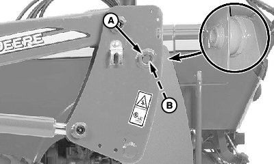
W22806-UN-08AUG12A - Bushing, Mast
B - Bushing, Frame
Make sure mast bushings (A) are aligned with frame bushings (B) on both sides of loader. -
W21211-UN-17NOV10Left-Hand Side Shown
A - Pin, Mast (2 used)
B - Spring Locking Pin (2 used)
Install pin (A) on both sides of loader. -
Fasten with spring locking pins (B).
-
W09734-UN-04SEP08Upper Hose Support
W20122-UN-29OCT08Lower Hose Support (Right-Hand Side—5M Series and 5105 ML Tractors Only)
A - Hose Support (upper)
B - Spring Locking Pin
C - Drilled Round-Head Blot
D - Hose Support (lower)
E - Spring Locking Pin
Right-Hand Side (If Equipped with Mid-Mount Couplers):-
Install upper hose support (A) on drilled round-head bolt (C) and fasten with spring locking pin (B).
-
5M Series and 5105ML Tractors only: Install lower hose support (D) on bracket, as shown, and fasten with spring locking pin (E).
-
|
OUO6064,0000FD4-19-20140217 |