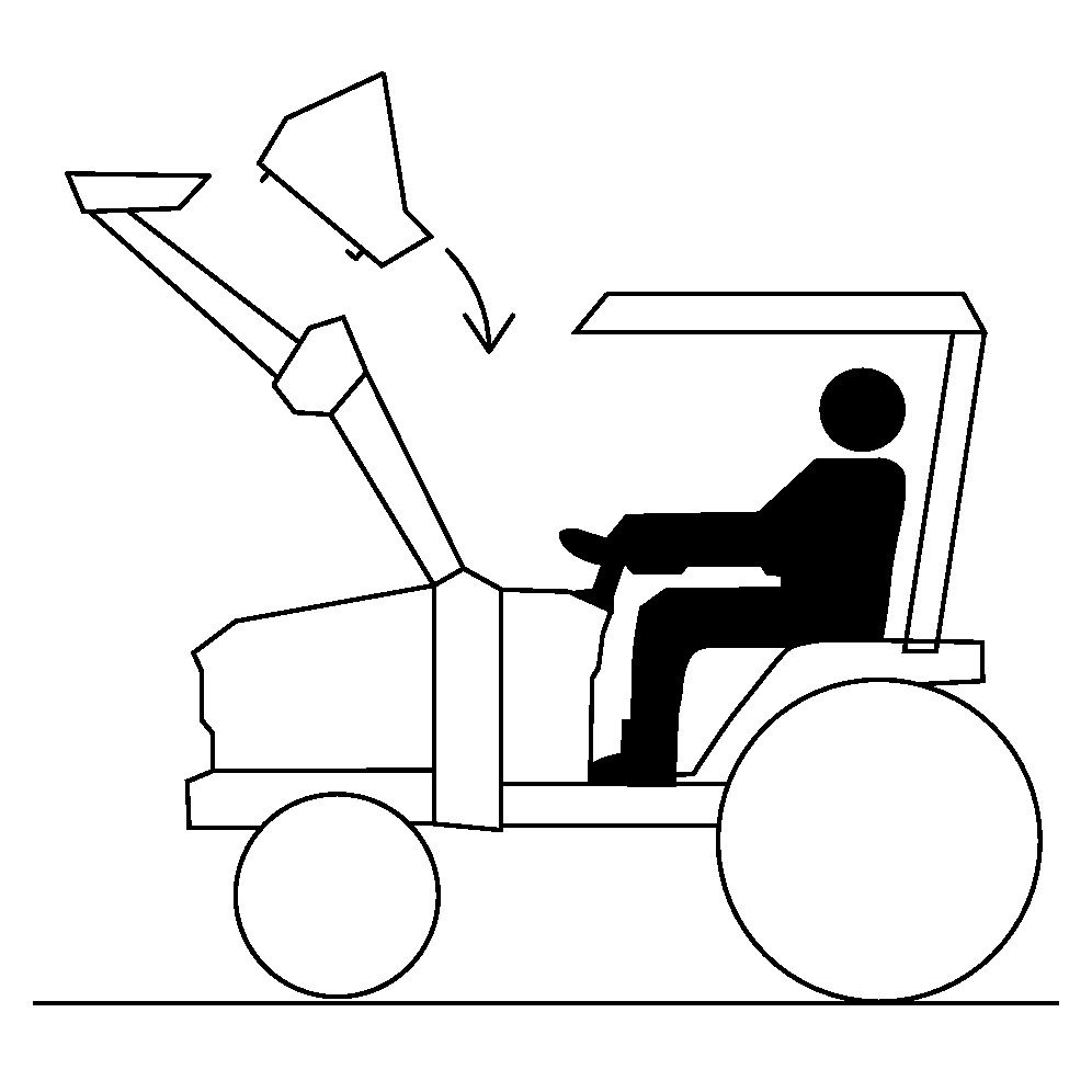
Attach Bucket or Attachment
Global Carrier Attachment
-
 CAUTION: DO NOT allow bystanders near loader while attaching
bucket/attachment.
CAUTION: DO NOT allow bystanders near loader while attaching
bucket/attachment.To prevent serious injury, bucket/attachment must be attached only by tractor operator.
Clean any debris off of latching mechanism, carrier, and attaching points.
-
Start tractor engine and extend bucket cylinders to angle carrier arms forward slightly.
-
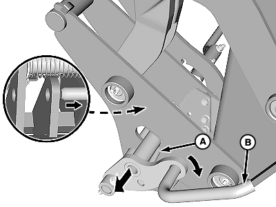
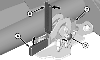
W24109-UN-28AUG13Latch Handle
A - Pin
B - Handle
Shut off tractor engine. -
Pull latch handle (B) outward and rotate down until pin (A) rests against carrier frame and latch is locked in UNLATCHED position.
-
Start tractor engine
-
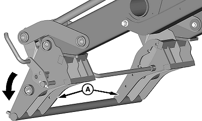
W24110-UN-09AUG13Full Extension
A - Arms
Extend bucket cylinders fully to angle carrier arms (A) downward. -
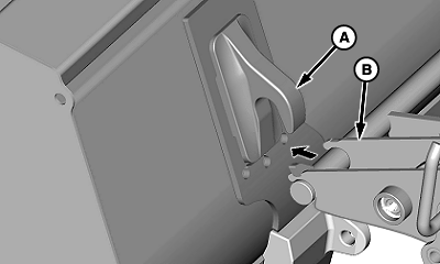
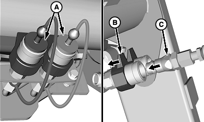
W24156-UN-13AUG13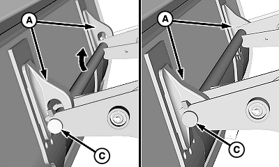
W24157-UN-13AUG13A - Arm
B - Hooks
C - Bar
Drive forward and center carrier arms (A) under hooks (B) on bucket/attachment. -
Raise carrier until bar (C) engages hooks on both sides of bucket/attachment.
-
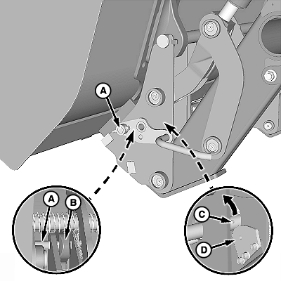
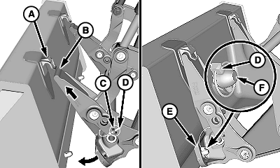
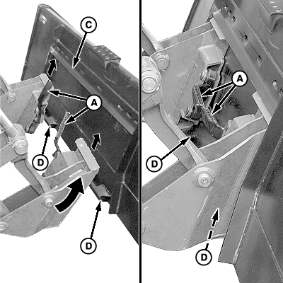
W24158-UN-28AUG13A - Pin (1 each side)
B - Bracket, Attachment (1 each side)
C - Rod
D - Tab
Roll back bucket/attachment fully (retract bucket cylinders). Rod (C) will contact tab (D) and release latch mechanism allowing pins (A) to slide into brackets (B) on bucket/attachment. -
CAUTION:
W08424-UN-14DEC06
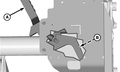
W24159-UN-28AUG13A - Latch Pin (1 each side)
DO NOT operate loader without making sure latch pins (A) are engaged with attachment. Failure to properly engage pins could cause attachment to detach from loader, resulting in serious bodily injury or death.Check pin engagement with bucket/attachment:
-
Position loader approximately 300 mm (12 in.) above ground and dump bucket/attachment until front edge contacts ground.
-
Apply pressure against ground (extend bucket cylinders) to verify pins (A) are fully engaged with bucket/attachment.
-
-
Lower loader to ground, place transmission in PARK, shut off engine, and remove key.
-
W24160-UN-13AUG13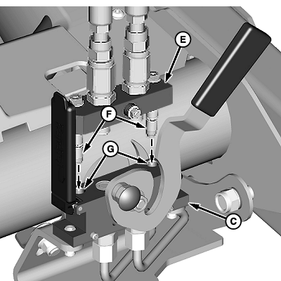
W24161-UN-14AUG13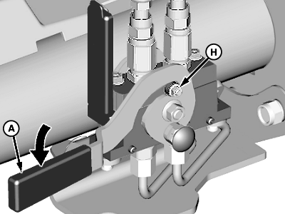
W24162-UN-14AUG13A - Lever
B - Cover
C - Coupler, Loader
D - Red Knob
E - Coupler, Attachment
F - Pins
G - Holes
H - Pin (1 each side)
If Equipped with Hydraulic-Operated Attachment, such as a Grapple, with multicoupler:-
Relieve pressure in hydraulic system. (See procedure in your tractor Operator’s Manual and RELIEVE HYDRAULIC PRESSURE SAFELY in Safety section).
-
Raise multicoupler cover (B).
-
Push red knob (D) IN and rotate lever (A) upward, as shown.
-
IMPORTANT: Multicoupler halves must be properly aligned or damage to couplers can occur.
Insert attachment coupler half (E) into loader coupler (C). Make sure locating pins (F) on attachment coupler fit into corresponding holes (G) in loader coupler.
-
Rotate lever (A) downward to engage pins (H) and lock coupler halves together.
-
-
NOTE: Hose connections are identified by matching the color-coded cap on the hose end with the same color-coded plug on the hydraulic lines:
- (A) Attachment Cylinder—Rod End (Green)
- (B) Attachment Cylinder—Head End (Orange)
W24163-UN-14AUG13A - Plugs
B - Coupler, Female
C - Coupler, Male
If Equipped with Hydraulic-Operated Attachment, such as a Grapple, with quick couplers:-
Relieve pressure in hydraulic system. (See procedure in your tractor Operator’s Manual and RELIEVE HYDRAULIC PRESSURE SAFELY in Safety section).
-
Remove plugs (A) from female couplers.
-
Push and hold collar on coupler (B).
-
Insert hydraulic hose connector (C) into coupler.
-
Release collar on coupler.
-
Repeat Steps c—e for remaining coupler (B) and hose connector (C).
-
Connect color-coded caps and plugs together.
500-Style Carrier Attachment
-
W24175-UN-28AUG13A - Hook (1 each side)
B - Carrier
C - Storage Position
D - Quick Lock Pin (1 each side)
E - Carrier Strap (1 each side)
F - Bucket Pin (1 each side)
Start tractor engine. -
Extend bucket cylinders to angle carrier (B) forward.
-
Align tops of carrier with hooks (A).
-
Raise loader until carrier engages hooks, then roll back bucket or attachment.
-
CAUTION: To avoid personal injury, make sure bucket or attachment
is properly secured to carrier.
Raise loader high enough to check that carrier straps (E) engage bucket pins (F) on both sides.
-
Place transmission in PARK and shut off engine.
-
Remove quick lock pins (D) from storage position (C).
-
Install quick lock pins (D) through bucket pins (F).
-
Lower loader to the ground.
Skid-Steer Carrier Attachment
-
IMPORTANT:
W08389-UN-29NOV06Left-Hand Lock Pin
W08390-UN-28NOV06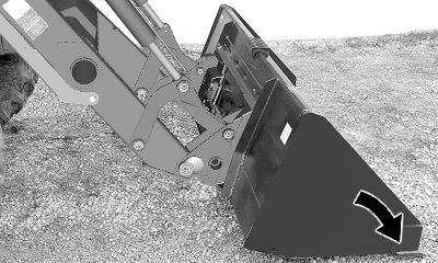
W24172-UN-28AUG13Tilt Bucket or Attachment Forward
A - Latch Handles
B - Lock Pin (1 each side)
C - Lip
D - Latches
Make sure both latch handles (A) are up and lock pins (B) are fully retracted.Raise both latch handles (A) into the UP (unlatched) position.
-
Start tractor engine and raise loader off ground.
-
Extend bucket cylinders to tilt carrier forward.
-
Slowly drive forward and raise loader, until carrier plates are positioned under lip (C) on bucket or attachment. Tilt bucket or attachment back (retract bucket cylinders).
NOTE: Bucket or attachment must rest against carrier plates.
-
Lower loader completely to the ground and shut off tractor engine.
-
Lower latch handles (A) to engage pins (B) with latches (D) on bucket or attachment.
-
CAUTION: Avoid personal injury. Ensure bucket or attachment
is properly secured to carrier.
Start tractor engine. Tilt bucket or attachment forward (extent bucket cylinders) to apply down pressure against ground and verify that pins (B) are fully engaged in latches (D).
NOTE: If bucket or attachment is not securely attached to the skid steer carrier, repeat Steps 1—7.
-
Lower loader to the ground and shut off tractor engine.
|
OUO6038,00021FC-19-20130828 |