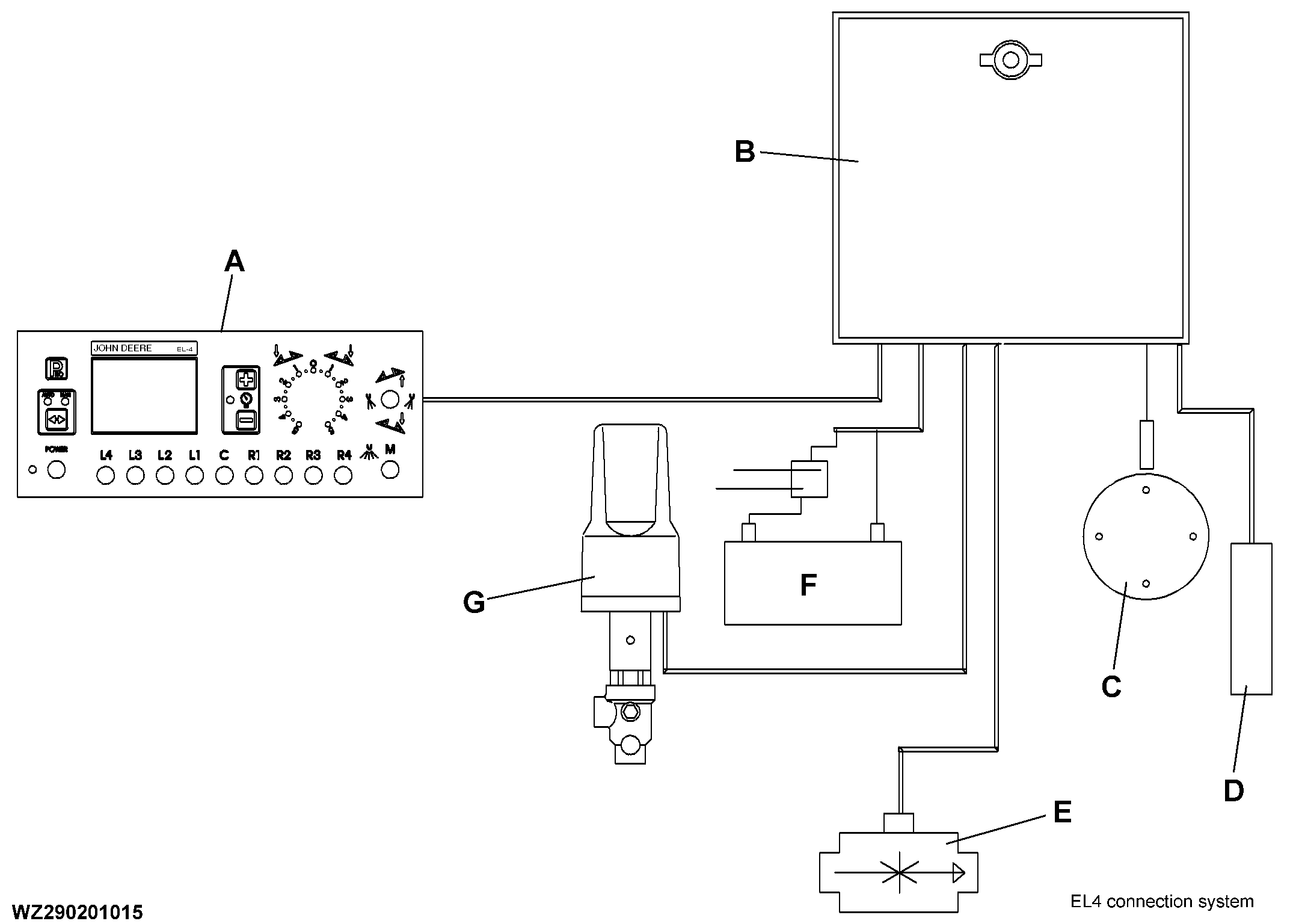
EL-4 Electrical Operation - Diagram
|
|
|
|
|
WZ00085,00000B9 -19-15AUG02-1/3 |
|
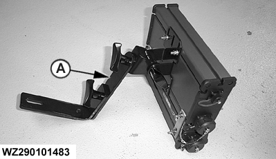
Fixing bracket
The control box must be fitted in the cab by means of the supplied fixing bracket (A) and must be easily accessible and visible.
|
|
WZ00085,00000B9 -19-15AUG02-2/3 |
|
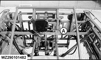
Wiring diagrams
The wiring diagrams are located in the receiver box of the machine (A).
|
|
WZ00085,00000B9 -19-15AUG02-3/3 |