Electrical Operation - Diagram
|
|
|
|
|
|
StarFire is a trademark of Deere & Company
| WZ00232,0000011 -19-16OCT06-1/3 |
|
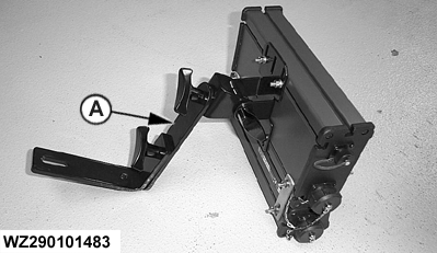
Fixing bracket
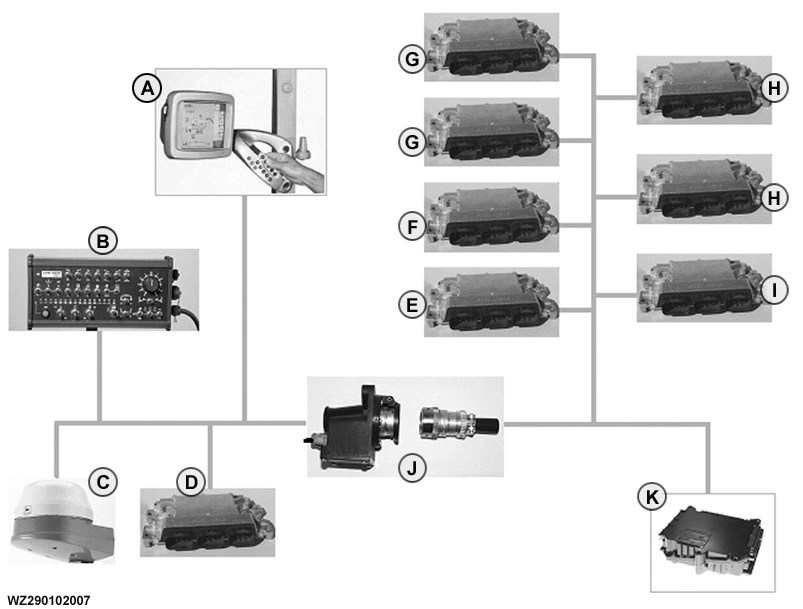
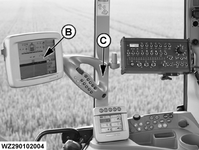
The control box must be fitted so that it is easily accessible and visible when securing with the supplied fixing bracket. The GreenStar 2 display (B) must be fitted into the cab by means of the supplied fixing bracket (C), which must be positioned in an easily accessible and visible place. More details can be found in the Operator's Manual of the GreenStar 2 display.
|
|
WZ00232,0000011 -19-16OCT06-2/3 |
|
Wiring diagrams
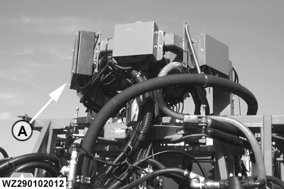
The wiring diagram is located in the receiver box (A) of the machine.
|
|
WZ00232,0000011 -19-16OCT06-3/3 |