Factory Settings
Factory Settings
|
To enter select softkey H "Machine Settings" and then "General Settings" tab. In the "Factory Settings - Enter Code" field, fill-in the access code and press "Enter" on the display control. Below are the new softkeys that are visible in the "Menu" field.
Softkey A
displays "General Factory Settings" screen with two tabs, "General Settings" and "Sensor Config.".
|
Softkey B
displays "Boom Settings" screen with two tabs, "Boom Settings 1" and "Boom Settings 2".
Softkey C
displays "Tank Settings" screen.
Softkey D
displays "Regulation Settings" screen with two tabs, "Regulation Settings 1" and "Regulation Settings 2".
Softkey E
displays "Alarm Settings" screen.
|
|
|
WZ00232,000003D -19-12OCT06-1/10
|
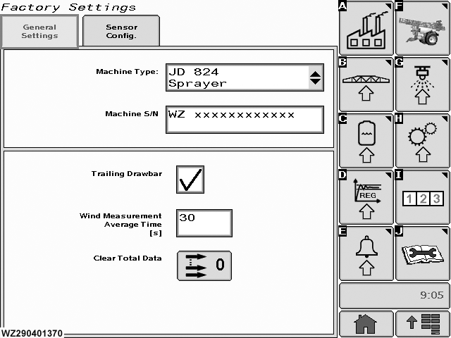
General Factory Settings - General Settings
General Factory Settings - General Settings
To view page select "General Settings" tab from "General Factory Settings" (Softkey A).
Machine Type
select the field to enter the machine type configuration drop down menu.
Machine S/N
enter the serial number of the machine in this field.
Trailing Drawbar
if the sprayer is fitted with an automatic trailing drawbar this field should be checked (ticked), otherwise it should be blank.
|
Select field with "enter" button, this toggles the state of the field.
Wind Measurement Average Time [s]
the time period for the wind speed measurement (if wind speed sensor is available) has to be entered here (via Keypad). A minimum duration (default = 30 seconds) is needed to compensate for changes of wind speed.
Clear Total Data
select to reset the "Total Data" memory to zero (cleared). The total data are displayed in the "Performance Data", select "Info" tab.
|
|
|
WZ00232,000003D -19-12OCT06-2/10
|
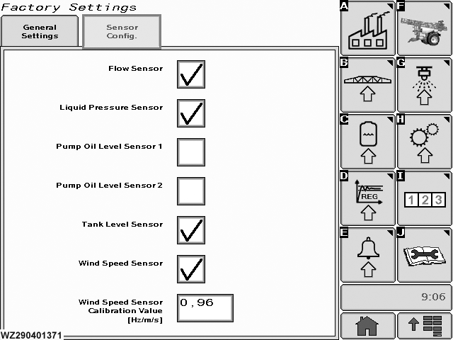
General Factory Settings - Sensor Config.
General Factory Settings - Sensor Config.
To view page select "Sensor Config." tab from "General Factory Settings" (Softkey A).
Flow Sensor
the presence of a flow sensor on the sprayer can be set here. If a flow sensor for regulation is fitted on the machine, tick the field otherwise leave blank.
Liquid Pressure Sensor
the presence of a liquid pressure sensor on the sprayer can be set here, tick the field otherwise leave blank.
Pump Oil Level Sensor 1 & 2
the presence of an oil pump(s) level sensor on the sprayer has to be
|
entered here. If one oil pump level sensor is fitted on the machine, tick "Oil Pump Level Sensor 1" field. "Oil Pump Level Sensor 2" should left blank for TwinFluid machine. The oil pump level control sensor(s) is/are only used for generating an alarm when the pump oil level is not OK.
Tank Level Sensor
if a tank level sensor is on the sprayer, tick the field otherwise leave blank.
Wind Sensor
if a wind speed sensor is fitted to the sprayer, tick the field otherwise leave blank.
Wind Speed Sensor Calibration Value [Hz/m/s]
enter the factory calibration value for the wind speed sensor with the numeric keypad.
|
|
|
WZ00232,000003D -19-12OCT06-3/10
|
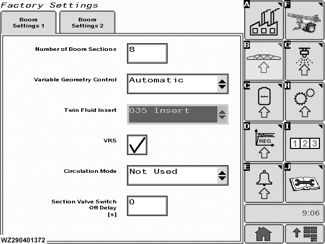
Boom Settings 1
Boom Settings 1
To view page select "Boom Settings 1" tab from "Boom Settings" (Softkey B).
Number of Boom Sections
enter the number of spray boom sections with the numeric keypad.
Variable Geometry Control
select the type of control for the Variable Geometry, "Not Available" when there is no Variable Geometry present, "Switch" to operate via the switch on the control box or "Automatic" if the Variable Geometry is controlled by BoomTrac (this function is not available yet).
Twin Fluid Insert
when the sprayer is fitted with the Twin Fluid System, the type of nozzle insert (035 or 042) has to be entered here. You can select between "035 Insert" and "042 Insert". This field will only show if a TwinFluid Machine has been selected in the "Machine Type" in "General Settings" menu.
VRS
the selection of the Vacuum Recirculation System (VRS) determines how the boom section
|
valves should be switched when switching off the master valve. If the sprayer is fitted with VRS, tick the field. When the Master valve is then closed, the boom section valves will remain open. When the sprayer is not fitted with VRS, leave the field blank. If the Master valve is then closed, the boom section valves will also close.
Circulation Mode
"Not Used" or "Semi Circul.". When the sprayer is fitted with a re-circulation system which creates a liquid flow back to the tank during spraying, "Semi-Circul." should be entered. If there is no re-circulation during spraying, then "Not Used" should be selected. For current John Deere sprayers, "Not Used" should always be selected, even if the sprayer is fitted with the VRS system.
Section Valve Switch Off Delay [s]
the time delay for switching off the boom section valves, after the Master valve is switched off can be entered here (not for sprayers with VRS) with numeric keypad.
|
|
|
WZ00232,000003D -19-12OCT06-4/10
|
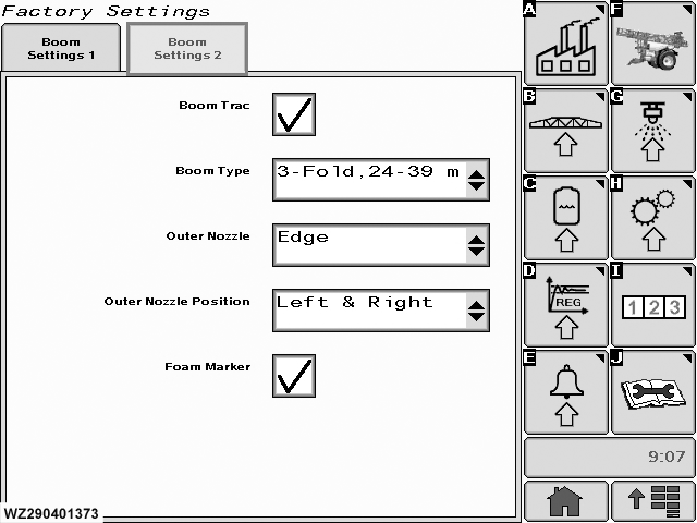
Boom Settings 2
Boom Settings 2
To view page select "Boom Settings 2" tab from "Boom Settings" (Softkey B).
Boom Trac
if this is fitted tick the field, otherwise leave blank.
Boom Type
select the type of Boom for the BoomTrac system from the drop down list.
|
Outer Nozzle
select the type of nozzle from the drop down list.
Outer Nozzle Position
select the position of nozzle(s) from the drop down list.
Foam Marker
tick this field if fitted. Icons will be present on "Sprayer - Main" page.
|
|
|
WZ00232,000003D -19-12OCT06-5/10
|
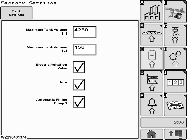
Tank Settings
Tank Settings
To view page select "Tank Settings" (Softkey C).
Maximum Tank Volume [L]
the maximum tank volume of the sprayer has to be entered here. This value is used as reset value for sprayers without a tank level sensor and as a maximum tank volume for calibrating the tank level sensor when fitted. A higher value than the maximum tank volume cannot be entered later by the operator to (automatically) fill the tank. If the tank needs to be calibrated the absolute value needs to be entered. To determine the maximum volume use a weighbridge or use a calibrated flow sensor.
|
Minimum Tank Volume [L]
this value is only used when there is a tank level sensor available. This is the level used for the minimum tank level calibration in the "Minimum Tank Alarm Level" menu (in "Machine Settings") and depends on the tank shape and position of the tank level sensor.
Electric Agitation Valve
tick this field if the valve is fitted, otherwise leave blank.
Horn
tick this field if it is fitted, otherwise leave blank.
Automatic Filling Pump 1
if an automatic tank filling system is fitted on the machine, tick the field otherwise leave blank.
|
|
|
WZ00232,000003D -19-12OCT06-6/10
|
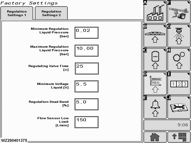
Regulation Settings 1
Regulation Settings 1
To view page select "Regulation Settings 1" tab from "Regulation Settings" (Softkey D).
Minimum Regulation Pressure [bar]
the minimum liquid pressure which the controller may adjust, has to be entered here (e.g. determined by the opening pressure of the non-return diaphragm valves in the nozzle holders). If this is pressure is reached during automatic control, a caution message "Minimum regulation pressure" will be shown.
Maximum Regulation Pressure [bar]
the maximum liquid pressure which the controller may adjust has to be entered here (e.g. determined by the maximum operating pressure of the machine). If this is pressure is reached during automatic control, a caution message "Maximum regulation pressure" will be shown.
Regulating Valve Time [s]
the speed of the pressure regulating valve has to be entered here. This is the time required to drive the valve from its minimum to its maximum position.
|
Minimum Voltage Liquid [V]
the minimum voltage at which the pressure regulating valve still can be rotated has to be entered here.
Regulation Dead Band [%]
the dead band around the target application rate (in percent) at which the controller must not regulate, has to be entered here.
Flow Sensor Low Limit [L/min]
the minimum flow rate in liters per minute at which the flow sensor (if fitted) still works accurately has to be entered here. When both a flow and a pressure sensor are available, then the controller will automatically switch to pressure based regulation when the flow measured by the flow sensor is lower than the flow sensor minimum value. This will be indicated by a caution message "Working pressure based (low flow)" in the "Sprayer - Main" screen. The controller will switch back to flow based regulation when the flow is above the low flow limit again (with 20% hysteresis). When only a flow sensor is available, a caution message "Low Flow Alarm" will appear on the "Sprayer - Main" screen, if the flow rate is below this value.
|
|
|
WZ00232,000003D -19-12OCT06-7/10
|
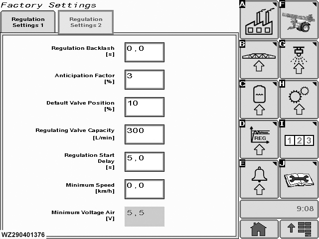
Regulation Settings 2
Regulation Settings 2
To view page select "Regulation Settings 2" tab from "Regulation Settings" (Softkey D).
Regulation Backlash [s]
the backlash of the liquid pressure regulating valve has to be entered here.
Anticipation Factor [%]
the position of the regulating valve is anticipated when turning boom section switches ON or OFF during turning on the headland with master valve OFF. This prevents a high start up pressure after closing a lot of sections and then switching the master valve ON. The controller uses the average speed of the last spray track as a basis for making the correction on the regulation valve. This last track should take at least 20 seconds to allow the controller to calculate a realistic average speed. Also when slowing down at the end of a spray track, the controller will move the regulating valve back to the flow corresponding with the average speed. The controller waits 5 seconds after switching the master valve to the OFF position before the anticipation starts, and the
|
anticipation handling stays active for maximum 10 minutes. The strength of the anticipation can be changed with an anticipation factor between 0% and 100%. When 0% is entered then the anticipation handling is disabled.
Default Valve Position [%]
on start up of the controller and after 10 minutes of non spraying activity, the regulating valve is moved to a default position. This default position is programmable and has a value between 0% and 100%. When 0% is entered then this feature is disabled. Moving the valve to its default position is done by first turning the valve to the lowest flow position (the controller uses the total valve turning time for this action), then the valve is moved to the default position. e.g. when 30% is entered and the valve time is 6 sec, then the valve is first turned in negative direction for 6 sec and then for 1.8 sec in positive direction.
Regulating Valve Capacity [L/min]
the maximum flow capacity of the regulating valve (completely open) at a pressure drop of 0.35 bar has to be entered here. This value is used for the normal regulation and also during anticipation.
|
|
|
WZ00232,000003D -19-12OCT06-8/10
|
|
Regulation Start Delay [s]
a regulation start delay can be programmed. The regulation is started after a small delay when switching the master ON (default = 0.3 sec). If 0.0 sec is entered, then the regulation start delay is disabled.
Minimum Speed [km/h]
the controller automatically stops spraying when the speed becomes lower than this programmable minimum speed. The controller will close the main valve when the speed
|
drops below the minimum speed. At the same time a caution message "Below Minimum Speed" will be shown. This feature can be disabled by entering 0.0 km/h (default) as minimum speed.
Minimum Voltage Air [V]
the minimum voltage at which the air pressure regulating valve still can be rotated has to be entered here (TwinFluid sprayers only).
|
|
|
WZ00232,000003D -19-12OCT06-9/10
|
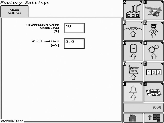
Alarm Settings
Alarm Settings
To view page select "Alarm Settings" (Softkey E).
Alarm settings can be entered here:
Flow/Pressure Cross Check Level [%]
if the sprayer is fitted with both a flow and a pressure sensor, a cross check can be performed between the measured and calculated flow rates. If the deviation between both values is larger than the
|
programmed cross check level (%) a caution message will be given "Flow / Pressure Cross Check Alarm". The desired deviation can be entered with the numeric keypad.
Wind Speed Limit [m/s]
the maximum wind speed allowed to spray with conventional nozzles (not with Twin Fluid) can be entered here. If the measured wind speed is higher than this wind speed limit, the controller will recommend the operator "STOP SPRAY, TOO MUCH WIND".
|
|
|
WZ00232,000003D -19-12OCT06-10/10
|
|