Fitting Electrical Socket to Tractor
IMPORTANT: The electric power supply must be connected in accordance with the wiring diagram and as described in this section.
Verify, before connecting the sprayer, Multi-Function Control lever (MFC) and GreenStar display, that the power supply is connected and functions as described.
Failure to follow these instructions can cause severe damage to the electrical system of the machine.
Always keep the battery well-charged (12 V minimum, 14.4 V maximum) and ensure the alternator functions properly.
CAN-Bus Wiring Harness
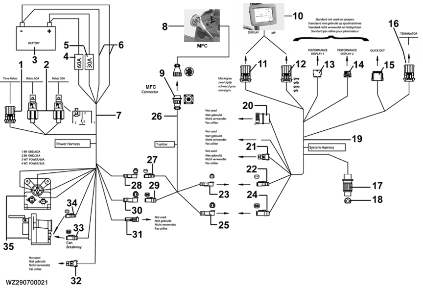
WZ290700021-UN-22MAR10
1 - Time Relay (not used)
2 - Main Relay
3 - Battery
4 - Fuse (60A)
5 - Fuse (30A)
6 - Ground Wire (brown)
7 - Power Harness
8 - Multi-Function Control (MFC)
9 - Connector (14 pole)
10 - GreenStar 2 terminal
11 - Grey/Black Plug (10-pole), GreenStar 2 Terminal
12 - Gray Plug, Mobile Processor
13 - Socket, Performance Display 1 (not used)
14 - Plug, Performance Display 2 (not used)
15 - Quick Out (for StarFire Receiver or ITC)
16 - Terminator
17 - Plug (3-pole Cobo)
18 - Socket (3-pole Cobo)
19 - System Harness
20 - Diagnostic Connector (not used)
21 - Implement Switch (not used)
22 - Plug (2-pole)
23 - Socket (2-pole)
24 - Plug (4-pole)
25 - Socket (4-pole)
26 - T-splitter cable
27 - Plug (2-pole)
28 - Socket (2-pole)
29 - Plug (4-pole)
30 - Socket (4-pole)
31 - Implement Switch (not used)
32 - Implement Switch (not used)
33 - Plug (4-pole, for T-Splitter at GreenStar-ready tractor)
34 - Plug (2-pole, for T- Splitter at GreenStar-ready tractor)
35 - Socket (9-pole Deutsch)
After verifying that the tractor power supply is operating correctly, the CAN-Bus wiring harness has to be installed in the tractor cab as shown in the drawing. This wiring harness is pre-assembled as far as possible. After the wiring harness is installed in the tractor cab, the remaining cables have to be connected to the tractor battery and the 9-pole ISO plug together with all separate plugs as follows:
- Install the pre-assembled main relays (2) on the tractor
- Connect the brown ground wires (6) to the negative pole (-) of the battery (3)
- Connect the white +12V-wires with 60A fuse (4) and 30A fuse (5) to the positive pole (+) of the tractor battery (3)
- Mount socket (35) on the back of the tractor and connect the cables as follows in the socket:
- Brown (Br/ground /60A) to position 1
- Brown (Br/ground/25A) to position 2
- White (Wt/+12V/60A) to position 3
- White (Wt/+12V/25A) to position 4
- Connect 2-pole socket (28) from the Power harness (7) to 2-pole plug (27) from the T-splitter cable (26)
- Connect 2-pole plug (34) to socket (35)
- Connect 4-pole plug (33) to socket (35)
- Mount 14-pole socket (9) in the tractor cab near the position where the Multi-Function Control lever (MFC) (8) has to be installed later
- Connect 2-pole socket (23) from the T-splitter (26) to 2-pole plug (22) from the System harness (19)
- Connect 4-pole socket (25) from the T-splitter (26) to 4-pole plug (24) from the System harness (19)
- Black/grey 10-pole plug (11) is used to connect the GreenStar 2 display (10)
- Grey 10-pole plug (12) is used to connect the mobile processor (not available with GreenStar 2 displays)
- Terminator (16) indicates the end of this Can-Bus cable
- 2-pole plugs (21, 31 and 32) are not used as is the remaining brown wire and diagnostic connector (20) from the system harness.
- Connect 3-pole (Cobo) plug (17) to the 3-pole socket (18) in the tractor. See also in this section.
- Connect 4-pole socket (30) from power harness (7) to 4-pole plug (29) from T-Splitter (26).
The quick out connection (15) can be used for connecting the StarFire receiver/ITC via a spare cable to the Can line.
Plug (3-pole Cobo)

WZ290201437-UN-13DEC10
A - +12 V when engine running (Not on engine start, see important)
IMPORTANT: The electric power supply must be connected according to the wiring diagram and explanation as written in this section. Not following these instructions can cause severe damage to the electrical system of the machine.
The correct connection of the plug (item (17) in Fitting Electrical Socket to Tractor) is important for the proper operation of GreenStar 2 display.
- Connect the red +12V-wire (15/30) via 25 Amp. fuse to the plus (+) terminal on the battery.
- Connect the red +12V-wire (82) to the +12V power supply which is available when the machine is running. When the tractor is started, the 12V power supply must be switched off in order to turn off the system. There is a relay (NO) integrated on the printed circuit board.
- Connect the black ground wire to the negative terminal (-) of the battery.
The relay ensures voltage feed (via cable 15/30). Once the vehicle is started, the relay temporarily switches off the system (via cable 82) in order to prevent voltage differences. This must be verified with a voltage tester, before mounting the plug into the socket.
Always keep the battery well-charged (12 V minimum, 14.4 V maximum) and ensure proper functioning of the alternator.
CAN-Bus Wiring Harness (preassembled box)
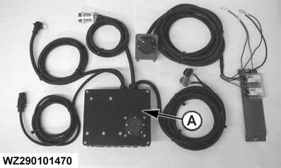
WZ290101470-UN-15MAR02
A - Preassembled Box
A kit with a preassembled box for quick and easy installation is available, to connect the sprayer with ISOBUS to different tractors.
This kit contains the preassembled box and a power supply cable with 9-pole socket for connection to the battery of the tractor. Connect the power supply cable with socket to the battery first:
- Mount the power socket with bracket at the rear of the tractor
- Connect the red wire to the positive pole (+) of the battery
- Connect the black wire to the negative pole (-) of the battery
The box (A) should be installed at the rear of the tractor. This box comprises the following connections:
- 9-pole ISO-11783 CAN socket: The CAN bus cable with 9-pole plug coming from the sprayer should be connected to this socket.
- Cable with 14-pole CAN bus socket: This cable should be connected to the cable with plug coming from the Multi-Function Control lever (MFC) in the tractor cab
- Cable with two 10-pole connectors (black and gray): The black connector should be plugged into the GreenStar 2 display socket in the tractor cab. The GS2 2600 has a 26-pin socket and requires an adapter cable, please use AL175883 harness for a Mannheim tractor. The gray connector is used for connection to the mobile processor (not available with GreenStar 2 displays).
- Cable with 3-pole 12-Volt COBO plug: This connector needs to be plugged into the 3-pole COBO socket in the tractor (see also item Power Supply in this section).
- Cable with 9-pole ISO-11783 connector (only used for power supply): This cable should be connected to the 9-pole power supply socket, previously installed at the rear of the tractor.
- Cable with 12-pole Deutsch connector : This cable can be connected (if available) to the 12-pole socket from the StarFire receiver. If required, an extension cable WZ8816134 is available to operate the sprayer together with other AMS applications
T-splitter cable used on GreenStar/ISO-ready tractors

WZ290101687-UN-01MAR05
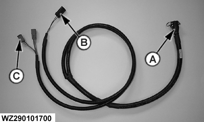
WZ290101700-UN-11APR05
A - 14-Pole Connector for MFC
B - 3-Pole Power Outlet
C - Plugs 4-Pole CAN Bus
The following T-Splitter cables are available:
- T-Splitter cable with connector for Multi-Function Control lever (MFC) for John Deere 6010 / 7010 / 8010 Series Tractors with GreenStar™ ready wiring harness. (Part number WZ8816141)
- T-Splitter cable with connector for MFC for John Deere 6020 Series Tractors with ISO/GreenStar™ ready wiring harness. (Part number WZ8816142)
- T-Splitter cable with connector for MFC for John Deere 7020 / 7030 / 8020 / 8030 Series Tractors with ISO/GreenStar™ ready wiring harness. (Part number WZ8816143)
- T-Splitter cable with connector for MFC for John Deere 6030 / 7030 Series Tractors with ISO/GreenStar™ ready wiring harness. (Part number WZ8816144)
To connect the T-splitter to a GreenStar/ISO-ready tractor, the side panel needs be removed to connect both 4-pole plugs (C) of the T-splitter to the 4-pole CAN Bus sockets. The power outlet plug should be connected to a power outlet available at the 6020 and 6030 series tractors (included in GreenStar-ready wiring harness). For the 7020, 7030, 8020 and 8030 the power outlet plug should be connected to the standard 3-pole power outlet plug inside the cab. Finally, the 14-pole connector needs to be connected to the MFC.
GreenStar is a trademark of Deere & Company | WZ00232,0000211-19-20101214 |