Shifting Transmission (Power Shift) |
|
|
|
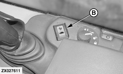
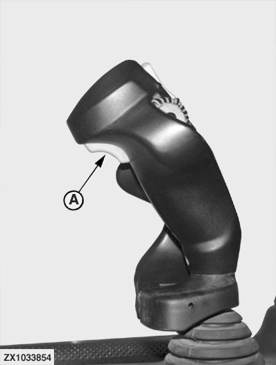
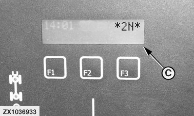
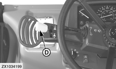
Transmission is controlled by means of FNR lever (D) and gear shift switches (A) or (B). The selected gear is indicated at digital display (C). When FNR lever (D) is moved first at start up, the second gear is automatically selected. You can select any other gear whilst FNR lever (D) is in neutral. IMPORTANT: Never operate FNR lever while machine is moving. If gear switches (A) and (B) are simultaneously pressed, the current gear will be held. Shifting From Neutral1. Run engine at idle speed. 2. Select gear. 3. Put FNR lever in desired position. 4. Accelerate engine. Changing Gears
|
|
OUCC020,000201A -19-21MAR05-1/6 |
|
NOTE: When the requested gear is over-ridden due to excess speed, the display will flash the current active gear. Changing Direction of Travel1. Reduce engine speed. 2. Brake slowly to a stop. 3. Put FNR lever in desired position. 4. Release brake. 5. Accelerate the engine. |
OUCC020,000201A -19-21MAR05-2/6 |
|
System Diagnostics
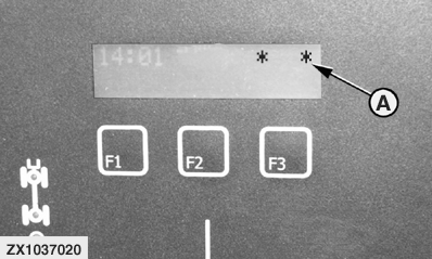
Gear shifting process is controlled by means of Transmission Control Unit (TCU). The gear indicator (A) at digital display can be used for basic diagnostics of the system as follows: 1. Check solenoid switches or wires between TCU and solenoid switches: When ignition is turned on, a TCU self-test is performed. If there is an internal error in one of the two TCU memories, the letter " E " will appear on the display (A), together with " N " for a ROM 1 error or " F " for a RAM 2 error. In both cases the control unit must be replaced. If both memories are OK, all connections and solenoids are then checked for shorted or open circuits. In case of a problem, the letter " E " for "Error" is displayed together with a second letter which specifies the error (problem) more precisely. For more details, see the table below. |
|
| Defective solenoid for | Displayed Character |
|---|---|
| Forward low | L |
| Forward high | H |
| Reverse | R |
| Clutch 1 | 1 |
| Clutch 2 | 2 |
| Clutch 3 | 3 |
| Error in ROM memory | N |
| Error in RAM memory | F |
OUCC020,000201A -19-21MAR05-3/6 |
|
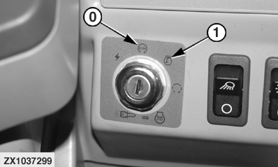
2. Check switches or wires between switches and TCU: a. With key switch in position (0), press the gear selector switch ("shift down") and hold in this position. NOTE: Either gear selector switch (A) or (B) may be used.
|
|
OUCC020,000201A -19-21MAR05-4/6 |
|
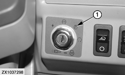
b. Turn start switch to position (1). The software version number is displayed for approx. two seconds. The left-hand field will then display a " T ", whereas the right-hand field will indicate the function of switches for trans-dump "d" , forward "F" , reverse "R" , handbrake applied "b" , shift up gears "U" , operator presence switch "O" and transmission lock (20 km/h) - option "T" . |
|
| Test Function | Left-hand field | Right-hand field |
|---|---|---|
| Trans-dump | T | d |
| Forward | T | F |
| Reverse | T | R |
| Handbrake applied | T | b |
| Shift up gears | T | U |
| Operator presence switch | T | O |
| Transmission lock (20 km/h) - option | T | T |
|
NOTE: The function "shift down gears" is verified when the display described above appears. If the function "shift down gears" does not operate correctly, the TCU will return to its normal operating mode. In this case use the second gear selector switch (not used previously) for checking switches or wires between switches and TCU. c. If the corresponding segment is not displayed for one or several functions, there is a fault in the relevant switch or in the wire between switch and TCU. Contact your John Deere dealer. |
OUCC020,000201A -19-21MAR05-5/6 |
|
3. Identifying the Software Version of the Transmission Control Unit (TCU) a.
Key switch in position (0). Press down gear selector switch (A) ("downshift") and keep in this position.
The software version number will appear on the display.
|
|
OUCC020,000201A -19-21MAR05-6/6 |
