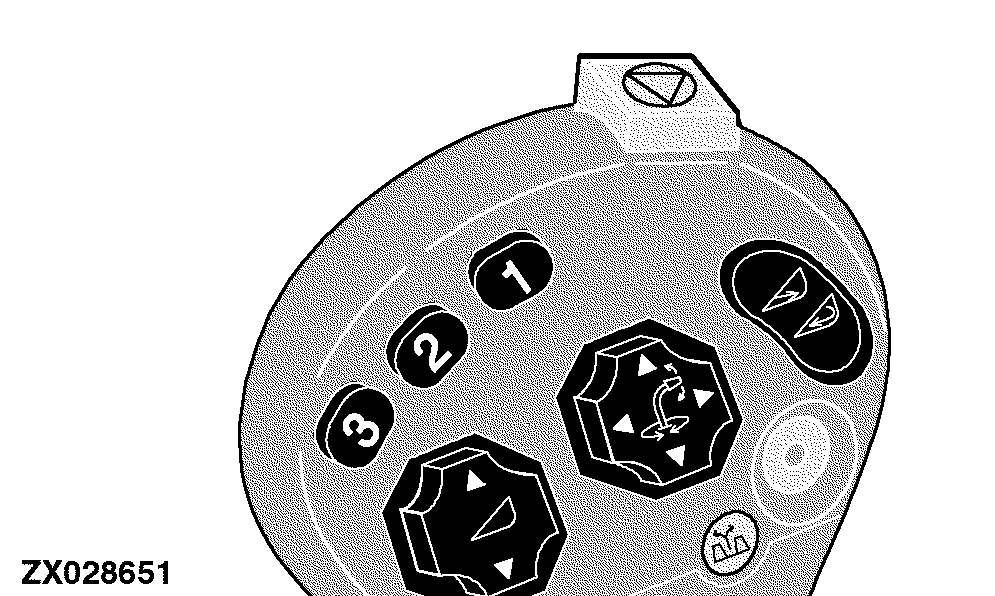
Automatic Header Control DisplayReturn to Position Display The automatic header control mode is activated by pressing one of two switches (1) or (2) located on the multi function lever. |
|
OUZXMAY,00003BA -19-10JAN06-1/8 |
|
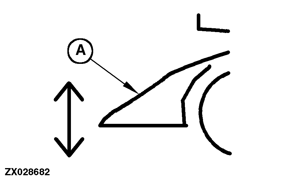
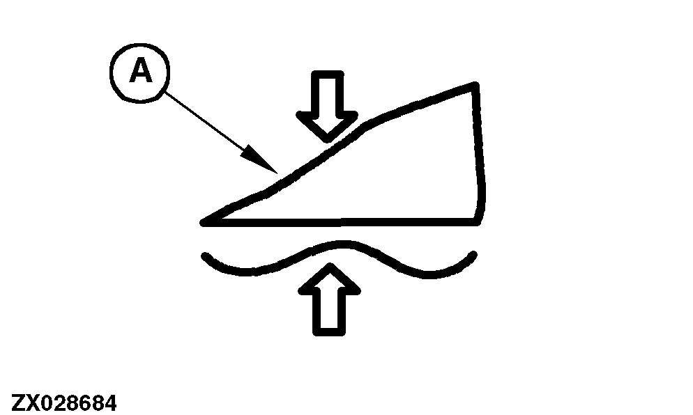
If the return to position mode is active (based on a CAN Bus message), the return to position icon (A) will be displayed. This icon indicates that the return to position mode is currently active.
|
|
OUZXMAY,00003BA -19-10JAN06-2/8 |
|
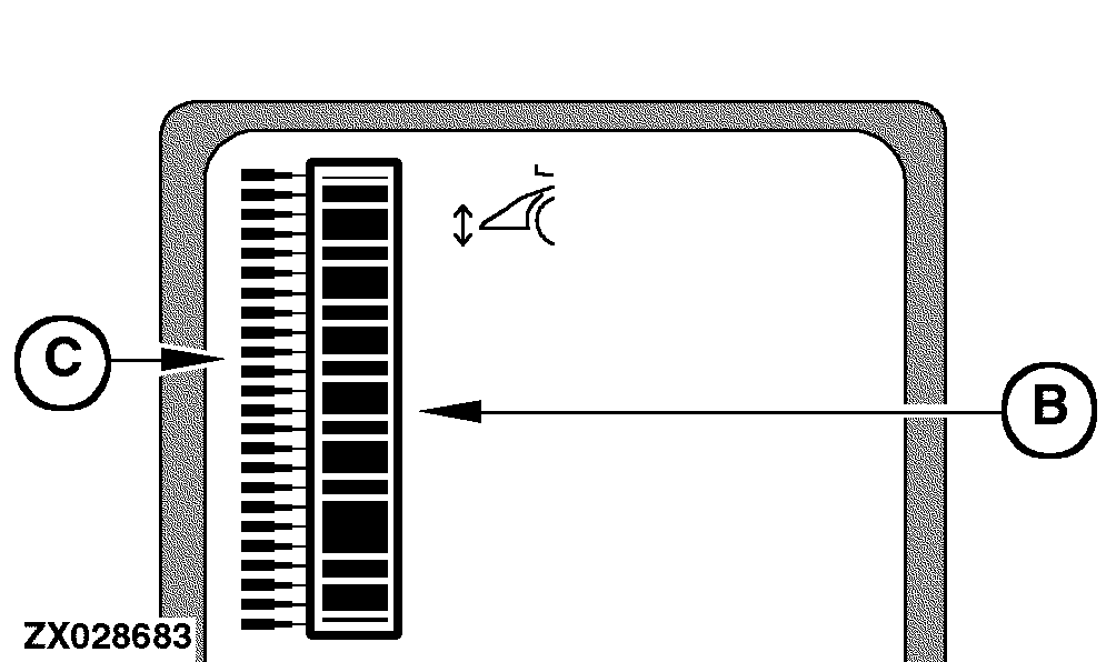
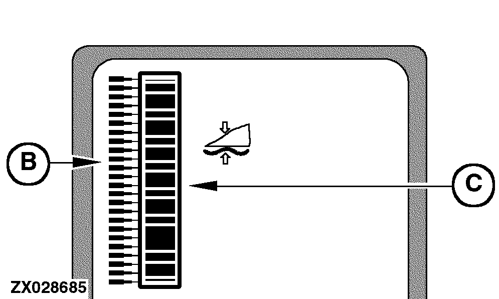
The inner bar graph (B) graphically represents the current header position with respect to the machine. The outer bar graph pointer (C) graphically represents the desired header position with respect to the machine. This information is provided via the CAN Bus from the SPFH main control unit.
For the desired header position, only the single outer bar graph pointer representing the desired position is displayed. To ensure that the inner bar graph (B) represents the maximum motion of the header that is currently in use, a calibration is required. This calibration determines which potentiometer readings correspond to the lowest and the highest header positions. Without doing this calibration, the bar graph display may not show the complete range of motion of the header. To calibrate the upper and lower header limit, use the following address:
NOTE: For detailed calibration information, see Section "Calibration Procedures" at the appropriate addresses. The digital display also gives header height information. |
|
OUZXMAY,00003BA -19-10JAN06-3/8 |
|
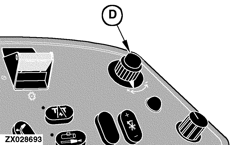
Return to Position - Operation While the return to position mode is active, change to the desired position setting can be made by turning the input control knob (D) located on the armrest. Only one bar graph pointer element is displayed at a time.
|
|
OUZXMAY,00003BA -19-10JAN06-4/8 |
|
Return to Pressure Display The automatic header control mode is activated by pressing switch (3) located on the multi function lever. |
|
OUZXMAY,00003BA -19-10JAN06-5/8 |
|
If the return to pressure mode is active, the return to pressure icon (A) will be displayed. This icon gives an indication that the return to pressure mode is currently active.
|
|
OUZXMAY,00003BA -19-10JAN06-6/8 |
|
Additionally, the previously stored desired pressure value is used to determine which pointer element on the outer bar graph (B) is displayed. When the return to pressure is first activated or reactivated, the digital display line displays the desired pressure value, for a maximum of 3 seconds or until another switch on the display is pressed. While adjusting the desired pressure setting (see Operation below), the digital display line continues to update the pressure value. The inner bar graph (C) is used to graphically represent the current pressure. To ensure that the inner bar graph represents the maximum pressure range of the header that is currently in use, a calibration is required. This calibration determines which pressure readings correspond to the operating range of the header. Without doing this calibration, the bar graph display may not show the complete range of pressure of the header. To determine the header type, use the following address:
NOTE: For detailed calibration information, see Section "Calibration Procedures" at the appropriate addresses. The digital display also gives header pressure information along with the appropriate units (bar or PSI). |
|
OUZXMAY,00003BA -19-10JAN06-7/8 |
|
Return to Pressure - Operation While the return to pressure mode is active, change to the desired pressure setting can be made by turning the input control knob (D) located on the armrest. Only one bar graph pointer element is displayed at a time.
|
|
OUZXMAY,00003BA -19-10JAN06-8/8 |