![]()
Introduction
Product Identification
Safety
Operating
Replacement Parts
Service Intervals
Service Lubrication
Service Engine
Service Transmission
Service Mower
Replacing Mower Drive Belt (38-Inch Mower)
Replacing Mower Drive Belt (Freedom 42)
Adjusting Mower Timing Belt Tension (Freedom42)
Replacing Mower Timing Belt And Adjusting Blade Timing (Freedom42)
Replacing Mower Drive Belt (48C Deck)
Checking for Bent Mower Blades
Servicing Mower Blades (38-Inch Deck)
Servicing Mower Blades (Freedom42)
Servicing Mower Blades (48C Deck)
Service Electrical
Service Miscellaneous
Troubleshooting
Storage
Assembly
Specifications
Warranty
John Deere Quality Statement
Service Record
Copyright© Deere & Company

Service Mower
Removing Mower
1. Park vehicle safely. (See Parking Safely in Safety Section.) Allow engine and muffler to cool completely.
2. Adjust mower cutting height to 25 mm (1 in).
3. Put wood blocks under each side of mower.
Put the lift lever in the mowing position before removing or installing the mower. |
4. Put lift lever in mowing position, bringing deck down onto blocks.

Picture Note: 38-Inch mower deck is used for photo purposes throughout this procedure.
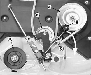
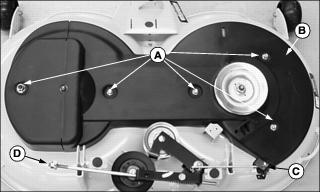
5. Remove belt from engine drive sheave and belt guides (A).
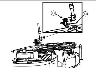
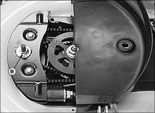
6. Remove spring locking pin and washer (B) to remove adjustment link and engagement rod (C) from arm.
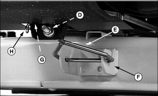
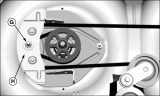
7. Remove spring locking pin (H) and long drilled pin (G) from front of mower.
8. Remove front draft rod (E) from tractor bracket hole (D) first, then front mower bracket (F).
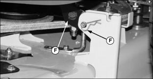
9. Remove spring locking pin and drilled pin (I) from both rear draft arms (J) and mounting brackets.
10. Move lift lever to the transport position to raise rear draft arms.
11. Remove wood blocks from both sides and slide mower out from under the tractor.
Installing Mower
1. Park vehicle safely. (See Parking Safely in Safety Section.) Allow engine and muffler to cool completely.
2. Check that mower cutting height knob is set at 25 mm (1 in).
3. Put lift lever in transport position.
4. Slide mower under the tractor.
5. Put wood blocks under each side of mower deck.
Put the lift lever in the mowing position before removing or installing the mower. |

6. Move lift lever to the mowing position to lower mower rear draft arms (A).
7. Fasten rear draft arms to mower mounting brackets with drilled pins and spring locking pins (B), on both sides of mower. Push spring locking pin all the way through as shown.
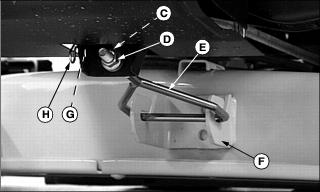
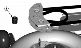
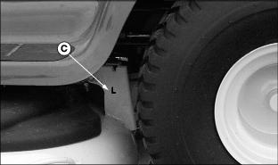
8. Install front draft rod (E) into front mower bracket (F) first, then tractor bracket top hole (C). Make sure rounded bushing (D) is on front side of tractor bracket.
9. Install long drilled pin (G) and fasten with spring locking pin (H).
IMPORTANT: Avoid damage! The belt will be damaged if installed wrong. Route the belt properly through belt guides. |
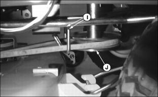
10. Put mower drive belt on engine drive sheave (J). Make sure belt is routed through both belt guide loops (I).

11. Check to make sure belt (K) is on all sheaves and idlers and is inside all belt guides (L).
12. Remove wood blocks from both sides of mower.
13. Move lift lever to mowing position and make sure mower engagement lever is pulled back into stop position.
14. Make sure mower is at lowest possible cutting height and that gauge wheels are not touching the ground.
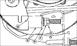
IMPORTANT: Avoid damage! If the mower engagement rod is not adjusted properly, the mower belt may slip or drag on blade sheave resulting in belt damage. |
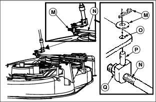
15. Check to see if adjustment pin (P) lines up with mower engagement arm hole (O).
· If pin does not line up, loosen lock nut (Q) and turn pin until pin slips freely into hole. Tighten lock nut.
16. Fasten adjustment pin (P) to mower arm with washer and spring locking pin (M).
Replacing Mower Drive Belt (38-Inch Mower)
NOTE: In this procedure the mower deck is removed for easier access. However, it is NOT necessary to remove deck when replacing belt.
1. Park tractor safely. Allow engine and muffler to cool completely.

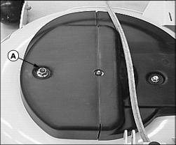
3. Remove three cap screws (A) and belt shield.

4. Loosen rear idler (B) and tensioning sheave (C).
7. Install new belt on mower as shown above.
8. Tighten rear idler and tensioning sheave.
9. Install belt shield and fasten with three cap screws.
10. Install mower deck and adjust mower engagement rod, if necessary.
Replacing Mower Drive Belt (Freedom 42)
1. Park machine safely. Allow engine and muffler to cool completely.
3. Remove self-tapping cap screws (C).
4. Move brake assembly (B) away from sheave (A) and drive belt.
5. Loosen idler (D) and tensioning idler (E) just enough to slip belt past the guides.
6. Remove drive belt and clean top of mower.
7. Install new belt on mower deck as shown.
8. Tighten idler (D) and tensioning idler (E).
9. Align brake assembly (B) with right spindle sheave (A) and fasten with self-tapping cap screws (C). Brake pad must seat against top of sheave.
10. Install mower and adjust mower engagement rod, if necessary.
Adjusting Mower Timing Belt Tension (Freedom42)
2. Move lift lever to mowing position and move to left side of mower.
NOTE: Mower timing belt cover can be unfastened and flipped open on the left side, exposing the tension adjustment mechanism, without having to remove the mower or the timing belt cover.
Picture Note: Mower removed for photo clarity.
3. Remove flange lock nut (A) to flip open left spindle cover.
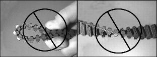
4. Check timing belt for damage. If the belt is damaged, replace the timing belt.
5. Remove top washer first, then loosen idler assembly center nut (B) ONE FULL TURN ONLY.
6. Check that blades are timed properly (90° from each other). If blades are out of time, set blades to proper timing.

7. Turn left spindle sprocket (C) to be sure belt is seated properly in the sprockets and idlers.
IMPORTANT: Avoid damage! Incorrect belt tensioning can cause belt damage. Do not over tighten belt tensioning spring assembly. |
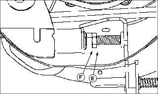
8. Loosen jam nut (D) and adjusting nut (E) so that there is a small air gap between washer (F) and mating surface of spring bushing (G).
9. Rotate adjusting nut (E) clockwise until washer (F) makes solid contact with the mating surface of spring bushing (G).
10. Tighten idler assembly center nut (B) to 87 N·m (64 lb-ft.).
11. Tighten jam nut (D) against adjusting nut (E) to 27 N·m (20 lb-ft.).
12. Turn left spindle sprocket (C) to be sure belt is seated properly in the sprockets and idlers.
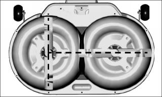
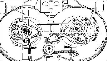
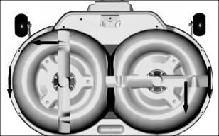
NOTE: The position of the drain holes in the spindle sheave (A) and the indentations in the timing sprocket (M) are in alignment with the mower blades (K) and (L).

13. Check that blades are timed properly (90° from each other). If blades are out of time, set blades to proper timing.
14. Install top washer on top of center nut (B) and close left spindle cover.
15. Fasten cover with flange lock nut and tighten to 14 N·m (10 lb-ft.).
Replacing Mower Timing Belt And Adjusting Blade Timing (Freedom42)
IMPORTANT: Avoid damage! Damage may occur to the belt or blades after a major blade impact: |
1. Park machine safely. (See Parking Safely in the Safety Section.) Allow engine and muffler to cool completely.
4. Check blade bolt torque anytime mower is removed. Carefully hold blade with glove, use a hand torque wrench, and tighten bolt to 57 N·m 42 lb-ft.).
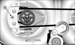
5. Move spindle brake assembly (C) and mower engagement rod assembly (D) back to clear timing belt cover.
6. Remove five flange lock nuts (A) and cover (B).
7. Turn jam nut (E) and adjusting nut (F) counterclockwise to end of threaded rod, and remove tensioning spring assembly.
8. Remove center nut and washer (G) and move fixed idler assembly (H) close to the spindle sprocket. DO NOT loosen other idler assembly hardware.
9. Raise idler assembly upward as you carefully remove timing belt from the left spindle sprocket.
10. Remove spacer (I) located between fixed idler assembly plates and carefully pull belt from assembly.

11. Loosen two belt guides (J) and rotate away from left sprocket.
12. Remove timing belt, replace if necessary.
NOTE: The position of the drain holes in the spindle sheave (A) and the indentations in the timing sprocket (M) are in alignment with the mower blades (K) and (L).

13. Position mower blades (K) and (L) 90° from each other.

14. Install new mower deck timing belt:
a. Route belt around right spindle sprocket (N) located under the mower drive belt sheave.

b. Route belt around outside of idlers and then in between the fixed idlers (O), pulling a belt loop through the idler assembly.
c. Insert spacer (I) between fixed idler plates and idlers.
d. Install the fixed idler assembly on the stud of the left support plate as you wrap belt loop around left spindle sprocket (P).

15. Install washer and center nut (G) on fixed idler assembly. Leave nut loose at this time.
16. Check that blades (K) and (L) are 90° from each other.
IMPORTANT: Avoid damage! Incorrect belt tensioning can cause belt damage. DO NOT over tighten belt tensioning spring assembly. |
17. Install tensioning spring assembly and adjust timing belt tension:
a. Align notch (Q) in idler assembly with tab on spring bushing (S).
b. Rotate adjusting nut (F) clockwise until the washer (R) makes solid contact with the surface of the spring bushing (S).
c. Turn adjusting nut an additional 1/2 turn to allow for new belt stretch. DO NOT over tighten.
d. Rotate right spindle sheave clockwise and observe that belt is riding properly in sprockets and idlers.
e. Tighten jam nut (E) against adjusting nut.
18. Tighten center nut (G) to 73 N·m (54 lb-ft.).
19. Install top washer on top of center nut.
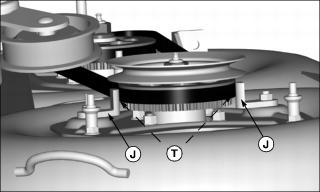
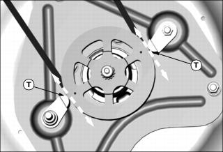
IMPORTANT: Avoid damage! Check belt guide-to-sprocket rim clearance. Measuring clearance incorrectly can cause belt or blade damage. |
a. Hold a 1 mm (0.039 in.) shim/gage between belt guides and sprocket rim, location (T), and rotate belt guides (J) clockwise against gage.
b. Tighten belt guide nuts to 24 N·m (18 lb-ft.).
Picture Note: Right spindle sheave removed for photo clarity.
c. Remove gage. Clearance (T), one on each side, should be 1contact belt guide.

21. Install timing belt cover (B) and fasten with five nuts (A). Tighten nuts to 14 N·m (10 lb-ft.).
23. Install mower and adjust mower engagement rod, if necessary.
Replacing Mower Drive Belt (48C Deck)
1. Park tractor safely. Allow engine and muffler to cool completely.

3. Remove six cap screws (A) and left and right belt shields.

4. Loosen sheaves (B) and (C).
6. Clean top of mower deck and sheaves.
7. Inspect belt for wear or damage; replace as necessary.
8. Install belt on mower deck as shown.
10. Install belt shields and fasten with six cap screws.
11. Install mower deck and adjust mower engagement rod, if necessary.
12. Move lift lever to transport position.
Adjusting Spindle Brakes
NOTE: This procedure applies only to the 38-Inch and 48C mowers.
The Freedom42 mower has a self-adjusting spindle brake assembly - no adjustment is necessary.
2. Adjust mower cutting height to 25 mm (1 in.).
3. Put lift lever in the mowing position.
4. Push mower engagement lever forward.

Picture Note: 38-Inch deck used for illustration.
6. Measure distance between brake pad surface (A) and pulley braking surface (B). Brake to pulley distance should be:


7. Turn adjusting nuts (E) on end of brake rods in correct direction to set brakes at proper distance from pulleys.
Checking for Bent Mower Blades
1. Park machine safely. (See Parking Safely in the Safety Section).
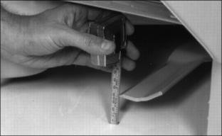
2. Put lift lever in mowing position.
3. Measure distance between blade tip and flat ground surface.
4. Turn blade. Measure distance between other blade tip and flat ground surface.
5. Install new blade, if the difference between the two measurements is more than 3 mm (1/8 in).
Servicing Mower Blades (38-Inch Deck)
Removing Mower Blades
1. Raise mower deck to gain access to mower blades. If necessary, remove mower deck after allowing engine and muffler to cool completely.
2. Block mower blade with a piece of wood to prevent it from spinning.
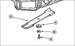
3. Loosen and remove cap screw (A), hardened washer (B), blade washer (C) and blade (D).
4. Inspect blades; sharpen, balance or replace blades as necessary.
Installing Mower Blades
1. Lubricate cap screw threads lightly with a general purpose grease or oil. This lubrication is to prevent rusting and seizing.
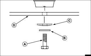
2. Position mower blade (D) with the cutting edge towards the ground onto the mower spindle.
3. Install blade washer (C) with cup side toward the blade.
4. Install hardened washer (B).
5. Install and hand tighten cap screw (A) until mower blade is in full contact (fully seated) with spindle.
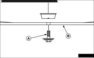
6. Block mower blade with a piece of wood to prevent spinning and tighten cap screws to 53 N·m (39 lb-ft.).
Servicing Mower Blades (Freedom42)
Removing Mower Blades
1. Hold mower blade with glove to prevent mower blades from spinning.
2. Raise mower deck to gain access to mower blades. If necessary, remove mower deck.
3. Loosen and remove bolt with washer (A), and blade (B).
4. Inspect blades; sharpen, balance or replace blades as necessary.
Installing Mower Blades
1. Check mower to be sure you are installing the blades on the correct side:
· The RIGHT and LEFT sides are marked on the rear draft brackets (C).
· There are direction arrows located on each outside edge of the mower. There is a RIGHT and a LEFT side blade. The blades are marked for identification.

2. Position mower blades (B) with the cutting edge towards the ground onto the mower spindle and align key on bottom of spindle with slot in blade.
3. Install and hand tighten bolt with washer (A) until mower blade is in full contact (fully seated) with spindle.
4. Hold mower blade with glove to prevent spinning, tighten bolts to 57 N·m (42 lb-ft.).
5. Check mower deck timing and adjust if necessary.
Servicing Mower Blades (48C Deck)
Removing Mower Blades
1. Raise mower deck to gain access to mower blades. If necessary, remove mower deck.
2. Block mower blade with a piece of wood to prevent it from spinning.

3. Loosen and remove bolt (A), washer (B) and blade (C).
4. Inspect blades; sharpen, balance or replace blades as necessary.
Installing Mower Blades
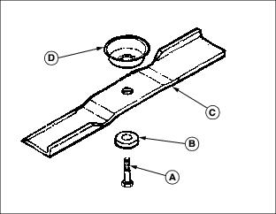
1. Check that deflector cup (D) is in place between spindle and blade.
2. Position mower blade (C) with the cutting edge towards the ground onto the mower spindle.
3. Install blade washer (B) with cup side toward the blade.
4. Install and hand tighten bolt (A) until mower blade is in full contact (fully seated) with spindle.
5. Block mower blade with a piece of wood to prevent spinning and tighten cap screw to 68 N·m (50 lb-ft.).
Sharpening Blades
Sharpen blades with grinder, hand file, or electric blade sharpener.
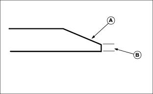
Keep original bevel (A) when grinding.
Blade should have 0.40 mm (1/64 in.) cutting edge (B) or less.
Balance blades before installing.
Balancing Blades
2. Put blade on nail in a vise. Turn blade to horizontal position.
3. Check balance. If blade is not balanced, heavy end of blade will drop.