![]()
Introduction
Safety Signs
Controls
Operating Machine
Operating Mower Deck
Lawn Care
Replacement Parts
Service Machine Safely
Service Interval Chart
Service Engine
Service Transmission
Service Steering & Brakes
Service 54 Inch Mower Deck
Service Electrical
Service Miscellaneous
Removing 54 Inch Mower Deck
Installing 54 Inch Mower Deck
Troubleshooting
Storing Machine
Assembly
Specifications
Service Statement
Copyright© Deere & Company

Installing 54 Inch Mower Deck
Installing The Mower Deck
1. Park the Front Mower safely.
3. Lift and latch the seat platform in the highest position.
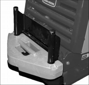
4. Place the mower deck in front of the Front Mower.
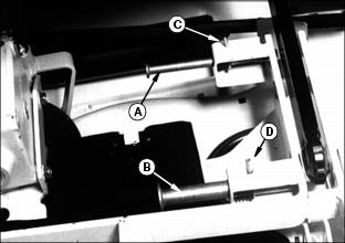
5. Pull out the spring pins (A and B) until latch pins (C and D) can be locked into slots as shown.
6. Hold the driveline up and push the mower deck under the Front Mower. Route the driveline and coupler up and over the top of the transaxle.
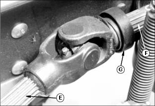
7. Connect the mower deck driveline (E) to the Front Mower PTO drive shaft (F) as follows:
· Push the coupler (G) onto the shaft (F). (It may be necessary to turn the mower deck driveshaft to align the spline of the two shafts.)
· Once the splines align and the driveshafts begin to couple, pull the coupler ring (G) forward and continue to push the mower deck driveshaft rearward onto the PTO shaft until the coupler locks in place.
· Push and pull the coupler until you are sure it is locked on the shaft.
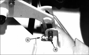
8. Remove the retainer ring (G) and the drilled pin (H) (if installed) from the rear of the mower deck on each side.
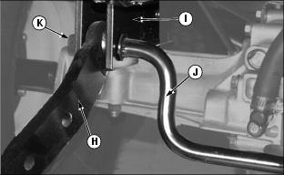
IMPORTANT: Avoid damage! Do not rotate the link (I) when you remove bracket (J) from the mower or install it on the shaft (K): You may change the mower level. |
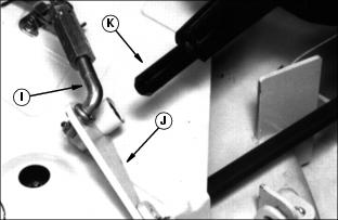
9. Lay each bracket (J) off to the side as shown.
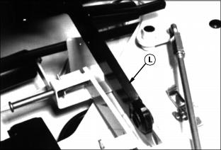
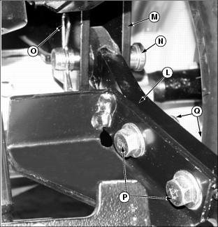
10. Push each lift arm (L) down into the mower deck frame.
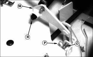
11. Install left and right side bracket (M) on each side of the lift arm shafts (N).
12. Install the drilled pin (O) on each side of the mower deck, and secure with retainer rings (P).
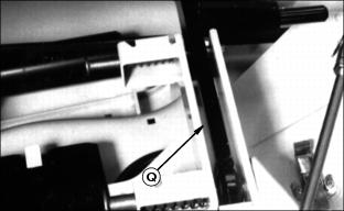
13. Check that left and right side lift arm (Q) is down into the mower deck frame.
14. Turn the crank to line up the front frame holes with the front push arm holes.
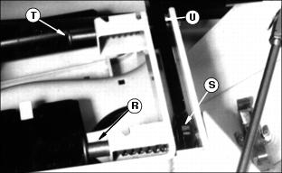
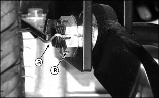
15. Turn the front spring pin (R) counterclockwise to release the latch pin from the bracket slot. The pin should snap into the lift arm hole (S). Repeat for other side of mower deck.
16. Turn the crank counterclockwise to line up the rear frame holes with the rear push arm holes.
17. Turn the rear spring pin (T) counterclockwise to release latch pin. The pin should snap into the lift arm hole (U). Repeat for other side of mower deck.
18. Adjust the cutting height and the rear mower wheel. (See "Operating 48 & 54 Inch Mower" section.)
Use Proper Ballast
Always install proper ballast when installing attachments onto the Front Mower to prevent tipping and loss of steering control when attachment is raised. Your John Deere dealer can provide the proper ballast for your attachment.
The 54 Inch Residential Mower Deck requires the following ballast:
Installing Lift Arms
1. Park Front Mower on level surface, park brake ON.
2. Push mower deck lift lever forward to extend lift cylinder. STOP engine.
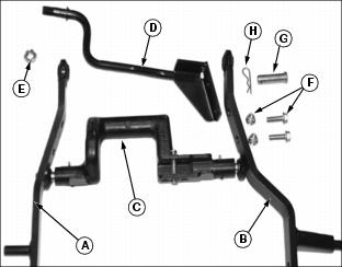
3. Assemble lift linkage as shown, with lift arms (A & B) attached to center rockshaft arm (C).
4. Remove rear pivot rod (D) if attached, by removing castle nut (E), and two cap screws and Nylock nuts (F) from lift arms.
5. Remove drill pin (G) and spring pin (H) from left lift arm.
6. Install the right lift arm (H) into the Front Mower hanger bracket (I). Install the rear pivot rod (J) through the hanger bracket and lift arm. Loosely install the castle nut (K) on the end of the rear pivot rod.
7. Install the left lift arm (L) into the Front Mower hanger bracket (M), and secure with drilled pin (N) and spring pin (O).
8. Install two cap screws (P) through rear pivot rod bracket and lift arm, and secure with two Nylock nuts (Q).
9. Tighten castle nut (R) on right end of rear pivot rod and install cotter pin (S) through rod and nut.

10. Raise the lift arms and install the drilled pin (T) through rockshaft casting and rod of lift cylinder. Install spring pin (U) through drilled pin.
See "Installing the Mower Deck" in this section for deck installation.