![]()
21-Inch Walk-Behind Rotary Mower
Introduction
Product Identification
Safety
Operating
Handle and Cutting Height Controls
Testing Blade/Engine Control Lever
Removing and Emptying Grass Bag
Replacement Parts
Service Intervals
Service
Troubleshooting
Storing Machine
Assembly
Specifications
Warranty
John Deere Quality Statement
Service Record

Operating
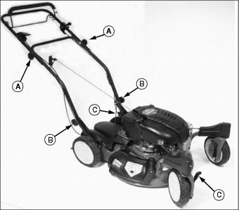
Engine Controls
Handle Controls
Handle and Cutting Height Controls
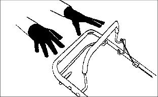
Locking Caster Wheels
NOTE: Caster wheels will not lock when mower is on an even surface. To lock caster wheels, push mower forward on an uneven surface, such as your yard.
Lock caster wheels when cutting on slope, cutting on rough or bumpy ground, or pulling mower backwards away from wall or out of narrow space.
To lock caster wheels:
1. Push mower forward on an uneven surface.
2. Pull lever (A) backward to lock position (B).
To unlock caster wheels:
1. Push lever (A) forward to unlock position (C)
Adjusting Cutting Height
NOTE: Adjust both levers to same height except for two lowest cutting heights (A and B on following chart). At two lowest cutting heights, raise rear lever one notch higher than front lever. This adjustment allows for increased air flow when bagging and side discharging, and provides a larger exit window for clippings when mulching.
Begin at upper cutting height, then adjust downward as desired, to avoid scalping lawn with too low a setting.
Highest cutting height for rear wheel is lever in furthest front position. Highest cutting height for front wheel is lever in furthest back position.
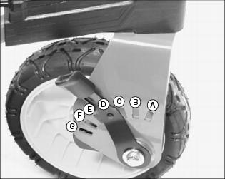
Adjusting front wheel height:
1. Lift front of mower deck slightly with one hand to take some weight off wheels.
2. Move height adjustment lever to desired position with other hand.
3. Repeat for other front wheel.
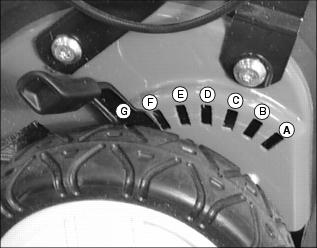
Adjusting rear wheel height:
NOTE: One height adjustment lever on left rear wheel adjusts both rear wheels.
1. Lift lower handlebar slightly with one hand to take some weight off wheel.
2. Move height adjustment lever to desired position with other hand.
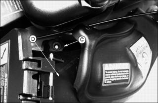
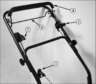
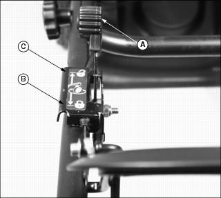
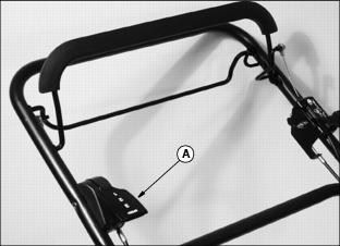
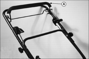
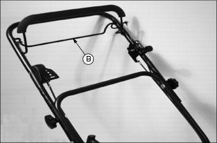
Adjusting Handle Height
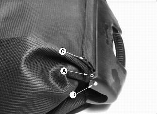
NOTE: If you are using a bagger with your mower, bag may prevent lowering of handle. Remove clip (A) to remove rod (B). Remove rod from lower position (C) and insert in upper position as shown to lengthen bag.
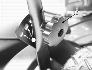
1. Remove knob (D) and bolt from handle.
2. Pivot handle to desired height.
3. Install bolt in one of three slots (E) and tighten knob (D) on handle.
Testing Safety Systems

Use the following checkout procedure to check for normal operation of machine.
If there is a malfunction during one of these procedures, do not operate machine. See your John Deere dealer for service.
Perform these tests in a clear open area. Keep bystanders away.
Testing Blade/Engine Control Lever
2. Release blade/engine control lever.
3. Listen for blade and engine to stop.
Starting Engine
Run engine only in a ventilated area. If engine is run in an enclosed area, open doors to bring in outside air. |
IMPORTANT: Avoid damage! To help prevent damage to recoil starter and band brake, do not start engine: · When blade is under load, such as operating in heavy grass. |
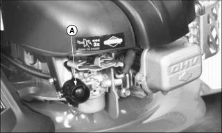
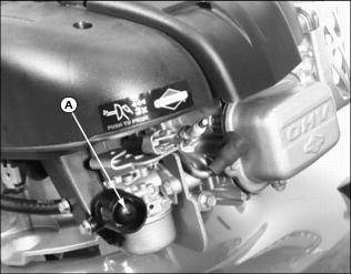
1. Prime engine by pressing primer bulb (A):
· Warm Engine - if engine does not start on first or second pull, press primer bulb 1 or 2 times
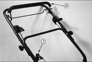
2. Hold blade control lever (B) against handle.
3. Pull starter handle (C) until you feel resistance. Then pull fast and steady.
4. Return handle slowly when engine starts.
Stopping Engine
Release handle and levers:
Selecting a Travel Speed
NOTE: It is normal for rear wheels to make a clicking noise when mower is manually pushed.
Travel speeds:
· 1st Gear: 3.1 km/h (1.9 mph)
· 2nd Gear: 3.9 km/h (2.4 mph)
· 3rd Gear: 5.0 km/h (3.1 mph)
To change travel speeds:
NOTE: Mower travel speed can be changed when the traction clutch lever is engaged and the mower is moving forward.
· Raise or lower speed control lever (A) to engage desired gear.
Operating the Machine
1. Hold blade control lever (A) against handle and start engine.
· Engine and blade will stop if blade control lever is released.
3. To begin mowing, pull and hold traction clutch lever (B) against handle while continuing to hold blade control lever against handle.
4. To stop forward motion or turn the machine, release lever (B).
5. Release both levers to stop forward motion, as well as the blade and engine.
Using Side Discharge Chute
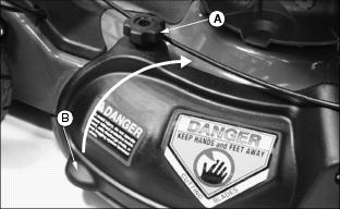
2. Remove mulch guard knob (A) from threaded stud.
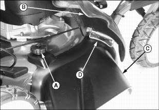
3. Lift and hold spring loaded mulch guard (B) up.
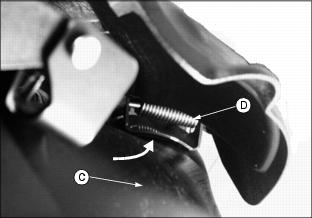
4. Install side discharge chute (C) under mulch guard spring and mounting bracket (D) and lower onto threaded stud.
6. Install and tighten knob (A) on threaded stud.
Installing Grass Bag
1. Remove mulch guard knob (A).
2. Lift and hold spring loaded mulch guard (B) up.
a. Slide bagging chute (C) into position under the mulch guard mounting bracket (D).
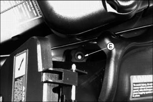
b. Lower bagging chute over stud. Install and tighten knob (E).
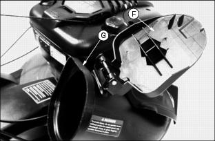
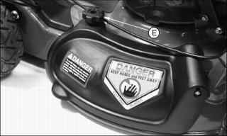
4. Open spring loaded bagging chute safety door (F).
5. Hang grass bag over bagging chute lip (G).
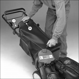
6. Hang upper grass bag (H) on mower handle (I).
Removing and Emptying Grass Bag
NOTE: Bag may wear and deteriorate. Check condition of bag often. Use a John Deere bag or equivalent to comply with safety specifications.
1. Release blade control lever to stop engine.
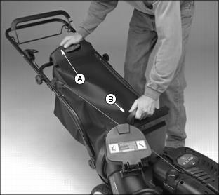
2. Grasp handle (A) and handle (B) from left side of mower. Lift bag off mower.
3. Lower front of bag and raise rear of bag. Shake bag to empty contents.