![]()
Introduction
Safety Signs
Controls
Operating
Replacement Parts
Service Machine Safely
Service
Troubleshooting
Storing Machine
Assembly
Specifications
Warranty
John Deere Quality Statement
Copyright© Deere & Company

Assembly
Identify Parts
Bag of Parts
Install Handlebar Assembly
NOTE: Remove all banding from the tiller assembly and remove protective wrap from the handlebar assembly before assembling. Remove the tiller from the shipping pallet before beginning assembly.

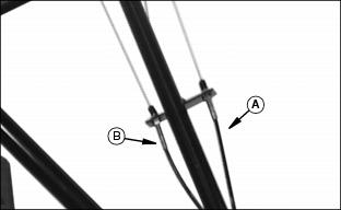
1. Cut tie strap (A) holding clutch cables (B) to the handlebar bracket.
2. Position handlebar legs on handlebar bracket (C) located at top of gearcase.
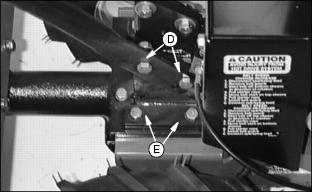
3. Three holes are available at the bottom of the handlebar for height adjustment. Select a safe, comfortable height. Align holes and install hardware. Install 3/8 x 1 inch bolt (E) from outside and install 3/8 washer and locknut (D) to bolt from inside.
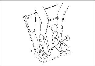
Connect Drive Cables
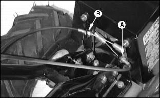
· FORWARD clutch cable (A) which is the shorter cable installed to the right side of the sheave housing.
· REVERSE clutch cable (B) which is the longer cable installed to the left side of the sheave housing.
2. Connect cables to handlebar bracket:
· FORWARD clutch cable (A) to outside of bracket. (will go to "F" Top Levers.)
· REVERSE clutch cable (B) to inside of bracket. (will go to "R" Bottom Lever.)
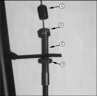
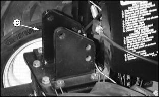
· Position cables in bracket about mid-way in threads (E).
· Secure cables to bracket by tightening nuts (D) against bracket.
· Put rubber boot (C) down over cable end. This will help to keep moisture out of cable.
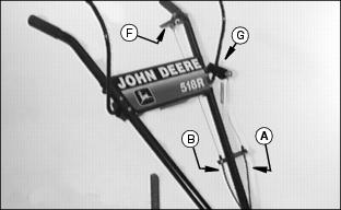
· FORWARD clutch cable (A) to "F" Top Levers (G).
· REVERSE clutch cable (B) to "R" Bottom Lever (F).
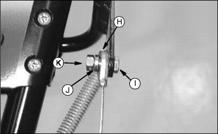
· When attaching cable ends use cap screws (1/4 x 3/4 in.) (I), cable spacers (J) and lock nuts (1/4 in.) (K).
· Tighten lock nuts, cable must be able to move freely around spacers.
4. Install tie strap to secure the cables to the handlebar just above the welded bracket on the handlebar.
5. Check for proper adjustments in the Main Clutch levers:
· "F" Top Levers - see Adjusting "Forward" Drive Belt Tension in the Service section.
· "R" Bottom Lever - see Adjusting "Reverse" Drive Belt Tension in the Service section.
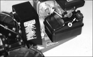
Add Engine Oil
NOTE: See Engine Oil in the Service Section for proper type of oil.
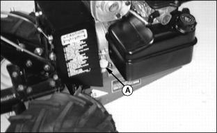
1. Remove oil fill plug (A). (Fill plugs are located on either side of the engine.)
NOTE: Crankcase capacity is approximately 0.56 L (19 oz.)
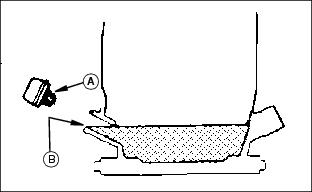
2. Slowly add oil into oil plug hole until crankcase is "FULL" (full oil level (B) indicated in illustration).
Remind customer to change oil in engine crankcase after first 2 hours of operation.
Check Tire Pressure
NOTE: Tires are overinflated at the factory to seal the bead.
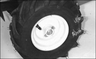
1. Inflate tires to 96 kPa (14 psi).
Check Gearbox Oil Level
IMPORTANT: Avoid damage! Serious damage can be caused to your transmission if it is allowed to run for even a short time without proper amount of oil. |
1. Position tiller on a flat level surface.
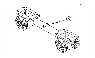
2. Remove the oil level (vent) plug (A).
3. Check oil level. Oil level should run out of or be up to check hole.
NOTE: Gearbox capacity is approximately 946 mL (32 oz.)
4. If necessary, add oil at the oil fill port (B). (See Gear Oil in SERVICE section for correct oil.)
5. Install oil level (vent) plug.
Remind customer to drain and refill gearbox after first 25 hours of operation or at the end of first season, whichever comes first.
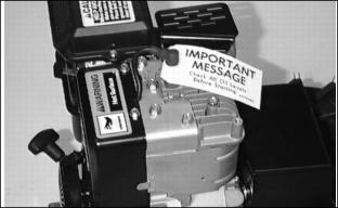
Fill Fuel Tank Safely
Add Fuel
1. Remove fuel cap (A) and "IMPORTANT" shipping tag.
2. DO NOT fill tank to top; fuel can expand.
Connect Spark Plug
IMPORTANT: Avoid damage! Start engine to check for proper operation before using. (See Starting in the OPERATING section for starting instructions.) |