for 4200, 4300, 4400 and 790 Compact Utility Tractors 59-Inch
Introduction
Safety Signs
Preparing Vehicle
Installing
Removing
Operating Machine
Service Machine Safely
Service
Troubleshooting
Storing Attachments
Assembly
Specifications
John Deere Service Literature
Quality Doesn't End When You Invest In A Deere
CopyrightŠ Deere & Company

Installing
Park Vehicle Safely
ˇ Stop vehicle on a level surface, not on a slope.
ˇ Before you leave the operator's seat, wait for engine and all moving parts to STOP.
Avoid High Pressure Fluids
ˇ Hydraulic hoses can fail due to physical damage, kinks, age, and exposure. Check hoses and lines regularly. Replace damaged hoses and lines.
ˇ Hydraulic fluid connections can loosen due to physical damage and vibration. Check connections regularly. Tighten loose connections.
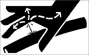
ˇ Escaping fluid under pressure can penetrate the skin causing serious injury. Avoid the hazard by relieving pressure before disconnecting hydraulic or other lines. Tighten all connections before applying pressure.
ˇ Search for leaks with a piece of cardboard. Protect hands and body from high pressure fluids.
ˇ If an accident occurs, see a doctor immediately. Any fluid injected into the skin must be surgically removed within a few hours or gangrene may result. Doctors unfamiliar with this type of injury should reference a knowledgeable medical source. Such information is available from Deere & Company Medical Department in Moline, Illinois, U.S.A. Information may be obtained from within the United States and Canada by calling 1-800-822-8262.
Install Snowblower
1. Park tractor on a hard, level surface.
2. Stop tractor engine, engage park brake and remove key.
3. Use safe lifting device to position snowblower in front of tractor.
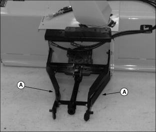
4. Place a block under the attachment arms (A) to align the snowblower to the front hitch.
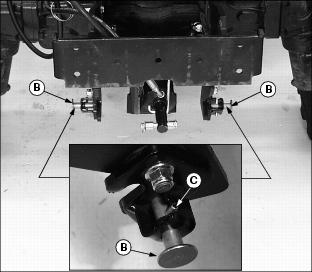
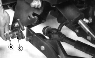
Picture Note: Photo to the right is the 4000 series tractor the photo below is the 790 series tractor.
5. Check position of tractor front hitch quick pull pins (B).
ˇ Quick lock pins on each side of front hitch must be pulled and rotated with each assembly roll pin (C) locking the quick lock pin in a retracted position.
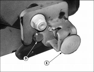
7. Slowly drive tractor forward until studs (D) fit into slots and spring pins (E) snap into place.
8. Check spring pins (E). Pins must be all the way in so snowblower is locked in place.
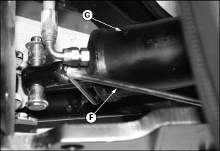
10. Slide wire support hanger (F) away from under lift cylinder (G) to allow lift cylinder to slide into position.
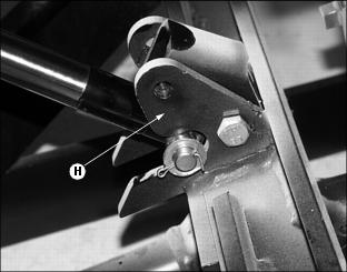
12. Use SCV lever to extend lift cylinder until cylinder rod slides into snowblower lift bracket (H).
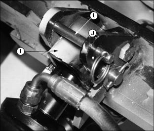
13. Close bracket latch (I) and fasten it with drilled pin (L) and spring locking pin (J).
14. Stop engine, move hydraulic control levers back and forth to relieve hydraulic pressure.
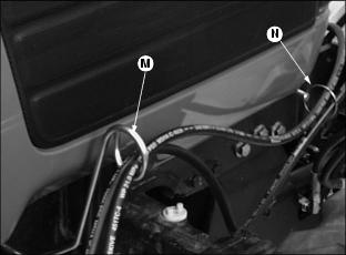
Picture Note: Photo m94632 is 4000 series tractor. Photo M43037 is 790 series tractor.
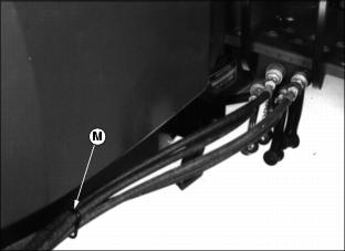
15. Route each snowblower hydraulic hose individually through wire support hanger (M) and wire ring support hanger (N) mounted to the tractor frame.
Picture Note: Photo M95631 is from 4000 series tractor. Photo M97692 is from 790 series tractor.
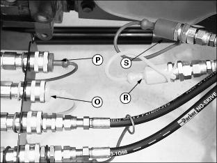
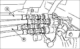
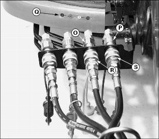
16. Remove dust plugs from couplers (O) and (P). Remove dust caps from hoses (R) and (S).
17. Slide coupler sleeve back on tractor couplers.
Picture Note: Photo M61547 is from 790 series tractor. Photo M94630 is from 4000 series tractor.
18. Put hose fitting into coupler and release sleeve.
NOTE: If necessary, refer to hydraulic outlet color coding and numbering sequence label (Q) attached to the tractor directly behind the SCV outlets.
19. Connect hose (R) (yellow) from cylinder rod end to coupler (O).
20. Connect hose (S) (red) from cylinder head end to coupler (P).
21. Install coupler dust plugs in hose dust caps.
23. Move SCV lever to all four positions to check for leaks. Check snow blower action to make sure hoses are connected to correct fittings.
25. Check transmission-hydraulic oil level. If necessary, add oil. (See your tractor operator's manual.)
26. Be sure hoses are not pinched or contacting other parts.
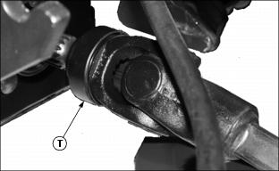
27. Remove PTO shaft cover. Install snowblower coupler (T) on tractor PTO shaft. Push locking collar to rear and pull shaft towards snowblower to be sure coupler is locked onto shaft.

