![]()
Introduction
Product Identification
Safety
Operating
Replacement Parts
Service Interval Chart
Service Lubrication
Service Engine
Service Transmission
Service Mower and Grass Collector
Adjusting Mower Deck Timing Belt
Replacing Mower Deck Timing Belt
Service Electrical
Service Miscellaneous
Troubleshooting
Storage
Assembly
Specifications
Warranty
John Deere Quality Statement
Service Record
Copyright© Deere & Company

Service Mower and Grass Collector
Removing Mower
1. Park vehicle safely. Disengage mower blades and wait for all moving parts to stop. (See Parking Safely in Safety Section.)
2. Adjust mower cutting height to lowest position.
3. Put wood blocks under each side of mower.
Put the lift lever in the mowing position before removing or installing the mower. |
4. Put lift lever in mowing position, bringing deck down onto blocks.
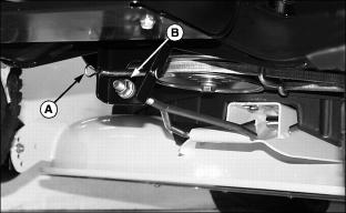
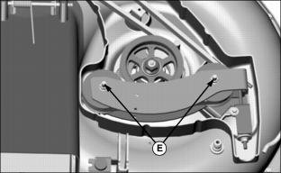
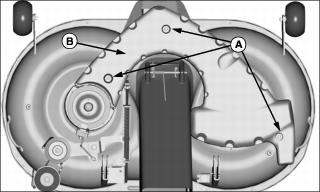
5. Remove spring locking pin (A) and pin (B).
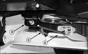
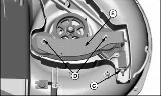
6. Move deck slightly forward and slide front draft rod (C) out of front tractor bracket (D) and deck bracket (E).
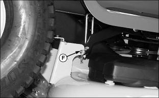
7. Remove spring locking pin and drilled pin (F) from rear draft arms, one on each side of tractor.
8. Remove wood blocks from each side of deck.
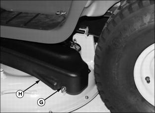
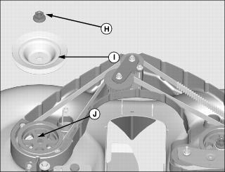
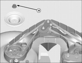
9. Remove nut and spacer (G) and drive belt cover (H) from left side of deck.
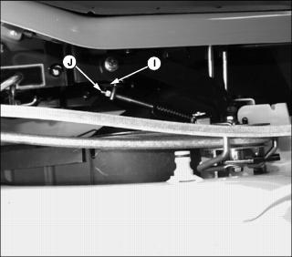
Picture Note: Mower engagement rod link is located on left side of mower deck.
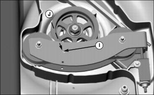
10. Remove spring locking pin and washer (I) from mower engagement rod link (J) and disconnect front of link from mower engagement rod arm.
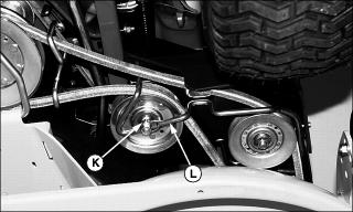
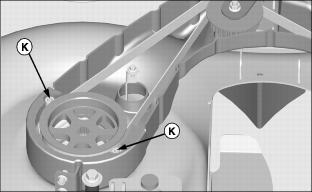
Picture Note: Tractor lifted for photo clarity only.
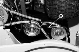
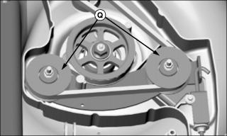
11. Remove nut (K) from idler belt guide (L).

12. Loosen nut (M) on idler belt guide.
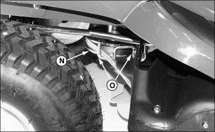
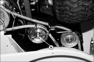
13. Remove belt from engine drive sheave (N) and belt guides (O) and idler belt guide.
14. Move lift lever to the transport position.
15. Push deck slightly forward to allow mower chute to drop from rear of tractor.
16. Hold plastic discharge chute down and slide mower out from under the tractor.
Installing Mower
1. Park vehicle safely. (See Parking Safely in the Safety Section.)
2. Put mower engagement lever in the off position.
3. Pull lift lever in transport position.
4. Adjust mower cutting height to the lowest position.
5. Slide mower under the tractor.
6. Align plastic discharge chute with rear opening in tractor. Mower chute should fit inside of tractor chute.

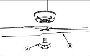
7. Slide front draft rod (A) into hole in bracket (B) in front of tractor and onto deck bracket (C).
8. Fasten with drilled pin and spring locking pin (D).
9. Put wood blocks under each side of mower deck.
Put the lift lever in the mowing position before removing or installing the mower. |
10. Move lift lever to the mowing position to lower mower draft arms.

11. Install rear draft arms, one on each side, to mower lift brackets with drilled pin and spring locking pin (E).
12. Remove wood blocks from both sides of mower.
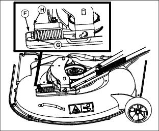
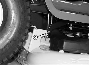
IMPORTANT: Avoid damage! If the mower engagement rod is not adjusted properly, the mower belt may slip or drag on blade sheave resulting in belt damage. |
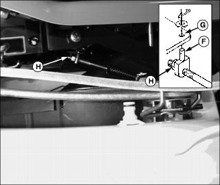
Picture Note: Mower engagement rod link is located on left side of mower deck.
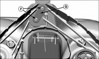
13. Check to see if pin (F) lines up with hole (G).
a. If pin (F) does not line up with hole (G), loosen lock nut (H) and turn pin clockwise to shorten linkage and counterclockwise to lengthen linkage until pin slips freely into hole.
b. Hold pin straight up and tighten lock nut (H).
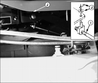
14. Attach front of mower engagement rod (I) with washer and spring locking pin (J).

15. Put mower drive belt on engine drive sheave (K). Make sure belt is routed through belt guides (L).
IMPORTANT: Avoid damage! The belt will be damaged if installed wrong. Route the belt properly through belt guides. |
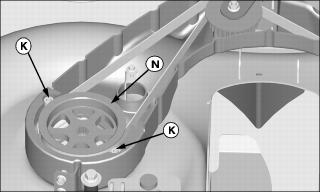
Picture Note: Front of tractor lifted for photo clarity only.
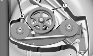
16. Route belt to the inside of belt guide (M) as shown.
17. Tighten nut (N) on belt guide and flat idler.
NOTE: Make sure belt is routed inside belt guide as shown.
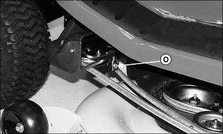
18. Tighten nut (O) on left side of belt guide.
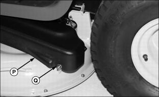
19. Install drive belt cover (P) on left side of deck and secure with spacer and nut (Q).
Replacing Mower Drive Belt
1. Park vehicle safely. (See Parking Safely in the Safety Section).
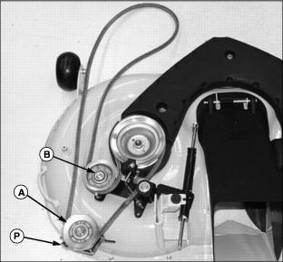
3. Loosen idler sheave (A) and flat idler (B).
5. Install belt on mower deck as shown.
6. Align bracket (C) by inserting locator into hole on deck bracket.
7. Tighten idler sheave and flat idler.
8. Install mower deck and adjust mower engagement rod, if necessary.
Adjusting Mower Deck Timing Belt
IMPORTANT: Avoid damage! Damage may occur to the belt or blades after a major blade impact: |
1. Park vehicle safely. (See Parking Safely in the Safety Section).
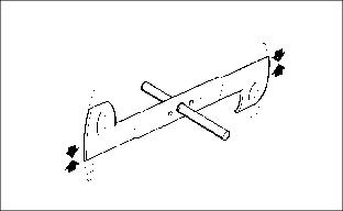
NOTE: If blades are not positioned at 90° as shown below, belt damage may have occurred and timing belt should be replaced.

Picture Note: Illustration above shows blades in correct (timed) position, 90° from each other.
3. Position mower blades (A) and (B) 90° from each other.
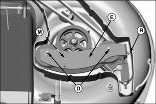
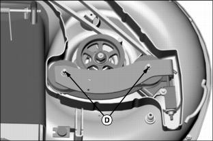
4. Remove three cap screws and washers (C) and remove cover (D).
5. Loosen two idler nuts (E) and then finger tighten.
6. Rotate adjusting nut (F) clockwise until end of tensioning spring (G) aligns with end of tensioner bracket (H).
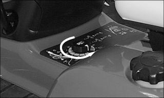
7. Turn blades several rotations and observe that belt is riding properly in sprockets and idlers.
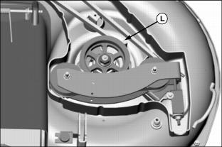
8. Place a screwdriver in slot (I) and rotate belt guide (J) clockwise until guide contacts belt and then counterclockwise 1/8 turn.

9. Tighten idler nuts (E) to 30 N·m (22 lb-ft).

10. Install cover (D) using three cap screws and washers (C).
11. Install mower deck and adjust mower engagement rod, if necessary.
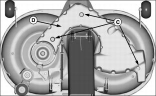
Replacing Mower Deck Timing Belt
1. Park vehicle safely. (See Parking Safely in the Safety Section).
2. Remove mower deck from tractor.
4. Remove three cap screws and washers (A) and remove cover (B).
5. Remove adjusting nut and washer (C), two nuts (D) and bracket (E).

6. Remove two idler nuts (F) and upper idler arm (G).
7. Block mower blade with a piece of wood to prevent it from spinning.
8. Remove nut (H) and drive sheave (I) and then hand tighten nut onto blade spindle (J) to prevent spindle shaft from dropping.
9. Remove two belt keepers (K) from left sprocket.

10. Remove belt keeper (L) and belt guide (M) from right sprocket.
11. Remove damaged mower deck timing belt.
12. Put new timing belt around LEFT sprocket (N) making sure teeth of belt are fully engaged in teeth of sprocket.
13. Hold belt in position and install two belt keepers (K), one on each side of left sprocket.
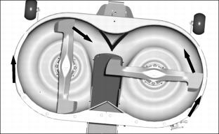
14. Route belt around center idlers as shown, install center bracket (G) and fasten with two nuts (F). Tighten nuts.
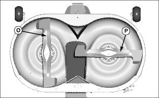
Picture Note: Illustration shows blades in correct (timed) position, 90° from each other.
15. Position mower blades (O) and (P) 90° from each other.
16. Route belt around right idlers and right sprocket (Q) as shown making sure teeth of belt are fully engaged in teeth of sprocket.
17. Install belt keeper (L) and belt guide (M) on right sprocket.
IMPORTANT: Avoid damage! Belt and blade damage may occur from an incorrectly installed drive sheave. Align drive sheave properly with blade spindle before tightening sheave hardware. |
18. Move idler arm to raise brake and install drive sheave on left blade spindle:
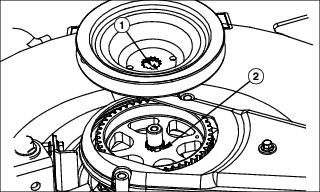
a. Align groove (1) in drive sheave with key (2) in left blade spindle.
b. Install nut (H) on blade spindle and tighten to 145 N·m (107 lb-ft)
19. Put end of idler arm (E) through hook of tensioning rod (R) and fasten to right idlers with two nuts (D). Make sure belt guide (M) is engaged in hole of idler arm. Do not tighten nuts.
20. Check that blades are still timed (90° from each other). If necessary, remove belt keeper (L), jump belt timing and reinstall belt keeper.

21. Compress idler arm at position (S) against strap (T) to allow installation of adjusting nut and washer.
22. Install adjusting nut and washer on end of tensioning rod.
23. Adjust tension on timing belt:
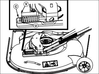
a. Rotate adjusting nut (C) clockwise until end of tensioning spring (U) aligns with end of tensioner assembly bracket (V).
b. Turn blades several rotations and observe that belt is riding properly in sprockets and idlers.
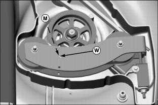
c. Put a screwdriver in slot (W) and rotate belt guide (M) clockwise until guide contacts belt and then counterclockwise 1/8 turn.
24. Tighten idler nuts (D) to 30 N·m (22 lb-ft).
25. Check that blades are still timed (90° from each other).

26. Install cover (B) using three cap screws and washers (A).
27. Install mower deck and adjust mower engagement rod, if necessary.
Servicing Mower Blades
Removing Mower Blades
2. Hold mower blade with glove to prevent mower blades from spinning.
3. Loosen and remove bolt with washer (A) and blade (B).
4. Inspect blades; sharpen, balance or replace as necessary.
Installing Mower Blades
1. Check mower to be sure blades will be installed on the correct side. The RIGHT and LEFT sides are marked on the rear draft brackets (C).
· There are direction arrows located on each outside edge of the mower. There is a RIGHT and a LEFT side blade. The blades are marked for identification.
2. Position mower blades (B) with the cutting edge towards the ground onto the mower spindle and align key (C) on bottom of spindle with slot (D) in blade.
3. Install and hand tighten bolt with washer (A) until mower blade is in full contact (fully seated) with spindle.
4. Hold mower blade with glove to prevent spinning, tighten bolts to 57 N·m (42 lb-ft).
5. Check mower deck timing and adjust if necessary.
Sharpening Blades
Sharpen blades with grinder, hand file, or electric blade sharpener.
Balance blades before installing.
Balancing Blades
2. Put blade on nail in a vise. Turn blade to horizontal position.
3. Check balance. If blade is not balanced, heavy end of blade will drop.
4. Grind bevel of heavy end. Do not change blade bevel.
Removing Grass Collector
· Park the machine safely and lock the park brake before getting off the seat. |
1. Park vehicle safely. (See Parking Safely in the Safety Section).
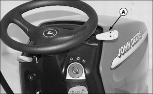
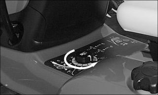
2. Pull mower engagement lever (A) back to disengage.
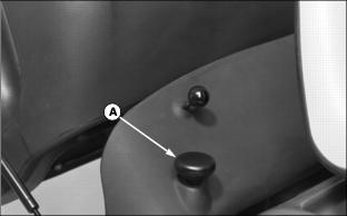
3. Push knob (B) down to open grass collector.
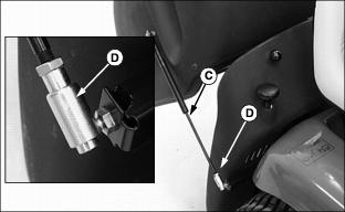
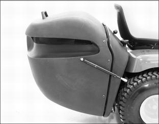
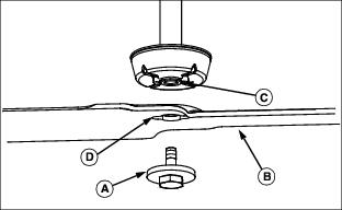
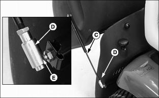
4. Disconnect gas cylinders (C) from tractor, one on each side.
· Move fastener (D) up and then pull out to release from stud.
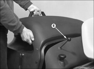
5. Pull release handle (E) up to unlock inside support brackets.
6. Lift grass collector off rear of tractor.
Installing Grass Collector
· Park the machine safely and lock the park brake before getting off the seat. |
1. Park vehicle safely. (See Parking Safely in the Safety Section).
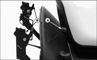
2. Pull release handle (A) out to put support brackets (B) in the unlocked (open) position.
3. Align inside bar of grass collector with open support brackets and set bar into brackets.
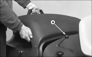
4. Push release handle (A) down to close support brackets.
5. Attach gas cylinders (C) to tractor, one on each side, by aligning slot in fastener (D) with ball joint (E) and releasing fastener down to close.