![]()
PIN (1600X010001) PIN (1620X010001)
Introduction
Product Identification
Safety
Operating Machine
Operating Mower Deck - 1600
Replacement Parts
Service Intervals
Service Lubrication
Service Engine
Service Transmission
Service Steering & Brakes
Service Mower Deck - 1600
Service Electrical
Service Miscellaneous
Troubleshooting
Storage
Assembly - 1620
Installing the Weight Transfer System
Installing and Removing Hydraulic Hoses to Mower Deck Lift Cylinder
Specifications
Warranty
John Deere Quality Statement
Service Record
Copyright© Deere & Company

Assembly - 1620
Installing Lift Arms
1. Park machine safely. (See Safety Section.)
3. Jack front of machine up until front tires are off of ground. Place hardwood blocks under frame, and lower machine off of jack.
4. Remove front wheels from machine.
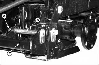
5. Remove M20 flange head hex nut (A).
6. Remove lift arm pivot pin (B) from rockshaft (C).
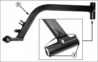
7. Locate left lift arm (D). Check that bushings (E) are installed on left and right side.
8. Remove tie strap from lift arm bushings.
9. Install left lift arm (D) onto rockshaft (E), making sure bushings remain in place.
10. Install lift arm pivot pin through rockshaft and lift arm, and secure with M20 flange head hex nut.
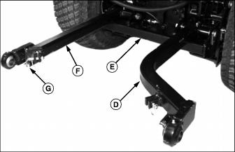
11. Repeat procedure for right side lift arm (F). Be sure stop bolt (G) is on bottom of lift arm before installing.
12. Install front wheels and lower machine off of blocks.
Installing Mower Deck
Picture Note: Left side lift arm is shown, right side lift arm is similar.
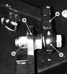
1. Align lift arms (A) with lift points (B) on mower deck frame.
2. Install one 1 x 5 in. hex head cap screw (C) through left side lift arm and mower deck. Secure with one 1 in. nylock hex nut (D).
3. Repeat for right side lift arm, using one 1 x 3-3/4 in. hex head cap screw, and 1 in. hex nut.
4. Grease lift arms at front and rear grease fittings.
Installing the Weight Transfer System
NOTE: The use of an overhead hoist is necessary to install weight transfer system on machine.
Mower deck upstop must be removed from machine before installing weight transfer system.
Mower deck must be installed on machine prior to installing weight transfer system.
1. Stop the machine on a level surface, not on a slope.
2. Lower the mower deck to the ground, then continue to hold the lever until the rockshaft reaches its lowest point, and stops moving.
3. Lock the park brake, stop the engine, and remove the key.
4. Remove the mower deck upstop, if installed.
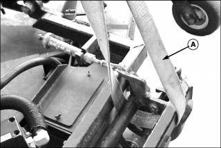
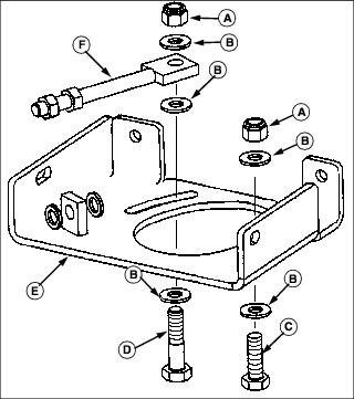
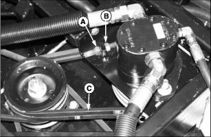
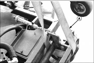
5. Position a strap (A) as shown. Make sure strap is rated at or above 454 kg (1000 lbs).

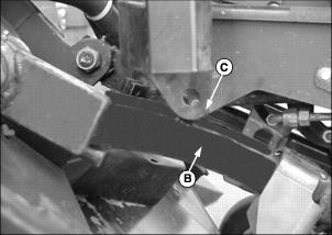
6. Lift the mower deck up with an overhead hoist until left lift arm (B) makes contact with the bottom of the operators platform (C).
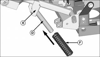
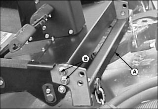
7. Install the undrilled end of the weight transfer tube (D) into the hole on the lift arm bracket (E).
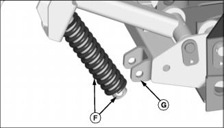
8. Slide the spring (F) up the tube until it makes contact with the lift arm bracket.
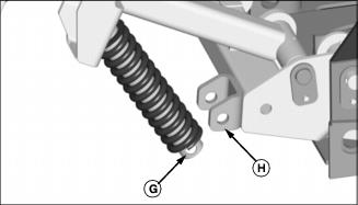
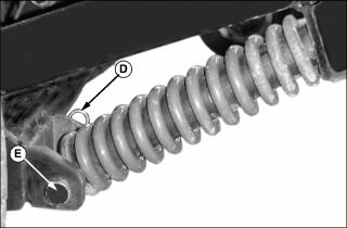
9. Holding the spring up against the lift arm bracket, pull the tube back out of the spring until the drilled hole (G) on the bottom end of the tube is below the bottom of the spring.
10. Place the bottom end of the tube into the bracket (H) on the rockshaft. LIne up the holes in the tube with the holes in the rockshaft.
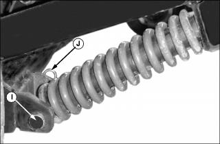
11. Install the drilled pin (I) through the rockshaft and tube, and secure with a spring pin (J). Rotate the spring so the flat spots on the bottom of the spring are centered on the pin.
12. Repeat steps six through ten for lift arm on other side of machine.
13. Lower hoist and mower deck to the ground. Remove strap.
14. Install mower deck upstop.
Installing Hydraulic Motor
Installing Motor to Motor Plate
Picture Note: Parts are shown from rear view.
A - Hex Head Nylock Nut - 1/2 in.
C - Cap Screw - 1/2 x 1-1/2 in.
D - Cap Screw - 1/2 x 2-1/4 in.
1. Install one 1/2 in. flat washer (B) on each of the 1/2 in. cap screws (C & D).
2. Fit motor mounting plate (E) up to hydraulic motor as shown, with left side motor mount tab (G) positioned between motor mounting plate and tensioner bolt (F).
3. Place one 1/2 in. flat washer (B) between left side motor mount tab, and tensioner bolt (F).
4. Install one 1/2 x 2-1/4 in. cap screw (D) (with washer installed from step one), up through motor mounting plate, left side motor mount tab, flat washer, and tensioner bolt.
5. Install one 1/2 in. flat washer (B), and 1/2 in. nylock hex nut (A) onto cap screw. Do not fully tighten at this time.
6. Install one 1/2 x 1-1/2 in. cap screw (C) (with washer installed from step one), up through motor mounting plate and right side motor mounting tab.
7. Install one 1/2 in. flat washer (B), and one 1/2 in. nylock hex nut onto cap screw. Do not fully tighten at this time.
Installing Motor Pulley
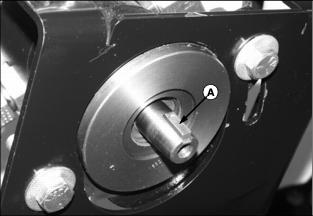
1. Install key (A) into keyway on hydraulic motor shaft.

2. Install motor pulley (B) onto motor shaft, aligning key in shaft with keyway on pulley.
3. Secure pulley with one 3/8 in. flat washer, 3/8 in. lock washer, and 3/8 x 1-1/2 in. hex head cap screw (C).
4. Tighten cap screw to 63 N·m (46 lb-ft).
5. Tighten set screw on pulley hub to hold shaft key in place.
Installing Mower Deck Belts
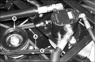
1. Install two drive belts (A) onto deck pulley (B) and motor pulley (C).
2. Lower motor plate down into mower deck frame and install three 3/8 in. cap screws (D) and one 1-1/4 in. cap screw (E) and flat washers to secure in place.
3. Secure left cap screw with one 3/8 in. flat washer and hex nut (F).
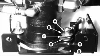
Tensioning Mower Deck Belt
1. Tighten belts by loosening jamb nut (A) and tightening tension nut (B) until mower belt tension at center of belt (C) is 4.8 mm (3/16 in.) of deflection with 31 N (7 lbs) force.
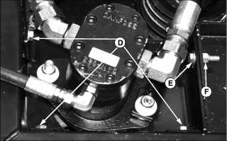
Installing and Removing Hydraulic Hoses to Mower Deck Lift Cylinder
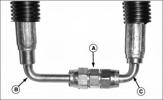
1. Locate hydraulic lift cylinder hoses from under machine. Remove hoses from shipping coupler (A).
NOTE: The head end hose has a large bend elbow (B) on the end of the hose. The rod end hose has a small bend elbow (C).
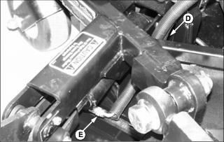
2. Route the rod end hose (small bend elbow) through the small triangular frame section (D) and connect to the rod end fitting (E) of the mower deck lift cylinder. Rotate hose fitting before tightening to avoid hose rubbing on frame.
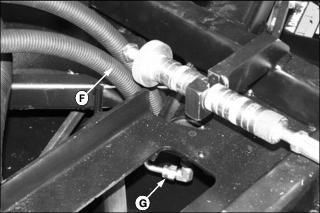
3. Route the head end hose (large bend elbow) through the triangular frame section (F) and connect to the head end fitting (G) of the mower deck lift cylinder.
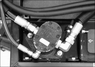
4. Turn hose fittings on hydraulic motor until routed as shown above.
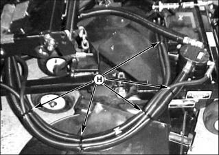
5. Install five tie-straps (H) around hydraulic hoses in positions shown.
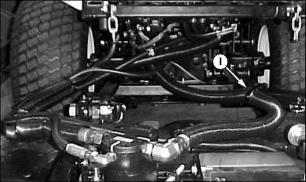
6. Attach left side hydraulic hose to left lift arm at (I) using one tie strap.
7. Removal is in reverse of installation. Lower deck to ground and stop engine before removing deck. Install caps on hose ends to prevent loss of fluid.
Installing Mower Deck Upstop
1. Install mower deck upstop (A) onto operator's platform as shown using four M12x30 flange head cap screws (B).
Removing Mower Deck
NOTE: The weight transfer system must be disabled prior to removing the mower deck.
The use of an overhead hoist is necessary to remove the weight transfer system from machine.
The mower deck upstop must be removed from the machine before removing the weight transfer system.
1. Stop the machine on a level surface, not on a slope.
2. Lower the mower deck to the ground, then continue to hold the lever until the rockshaft reaches its lowest point, and stops moving.
3. Lock the park brake, stop the engine, and remove the key.
4. Remove the mower deck upstop.
5. Position a strap (A) as shown. Make sure strap is rated at or above 454 kg (1000 lbs).
6. Lift the mower deck up with an overhead hoist until left lift arm (B) makes contact with the bottom of the operators platform (C). All tension should be off of weight transfer springs.
7. Remove the spring pin (D) and drilled pin (E) from the rockshaft.
8. Pull the spring and tube (F) out of the rockshaft bracket (G), and remove the spring and tube from machine.
9. Repeat steps seven and eight for other side of machine.
10. Lower hoist until mower deck to the ground. Remove strap.
11. Remove hydraulic hoses to mower deck lift cylinder. Cap hoses to prevent fluid loss.
12. Loosen hydraulic motor mounting bolts, and loosen belt tensioner.
13. Remove drive belt from motor pulley.
14. Remove hydraulic motor mounting plate, and pull hydraulic motor and hoses back from mower deck.
15. Remove two 1 in. hex head cap screws holding mower deck to lift arms. Pull deck from machine.