![]()
21-Inch Walk-Behind Rotary Mowers
Introduction
Product Identification
Safety
Operating
Handle and Cutting Height Controls
Testing Blade/Engine Control Lever
Replacement Parts
Service Intervals
Service
Troubleshooting
Storing Machine
Assembly
Specifications
Warranty
John Deere Quality Statement
Service Record

Operating
Handle and Cutting Height Controls
Adjusting Cutting Height
NOTE: Adjust both levers to same height except for two lowest cutting heights (A and B on following chart). At two lowest cutting heights, raise rear lever one notch higher than front lever. This adjustment allows for increased air flow when bagging and side discharging, and provides a larger exit window for clippings when mulching.
Begin at upper cutting height, then adjust downward as desired, to avoid scalping lawn with too low a setting.
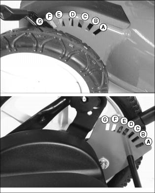
Picture Note: Front wheel shown in top photo.
Adjusting front wheel height:
1. Lift front of mower deck slightly with one hand to take some weight off wheels.
2. Move height adjustment lever to desired position with other hand.
Adjusting rear wheel height:
1. Lift lower handlebar slightly with one hand to take some weight off wheel.
2. Move height adjustment lever to desired position with other hand.
Adjusting Handle Height
Upper Handle:
NOTE: Upper handle height can be independently adjusted to two positions.
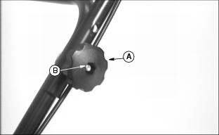
1. Remove knob (A) and bolt (B) from each side of upper handle.
2. Move handle to desired height.
3. Install bolt through matching holes in upper and lower handles on each side.
4. Install and tighten knob (A).
Lower Handle:
NOTE: Lower handle height can be independently adjusted to three positions.
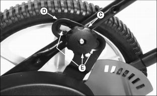
1. Loosen knob (C) approximately 25 mm (1 in.) on each side of handle.
NOTE: Knob must travel within slotted adjustment brackets and come to rest within one of the three height setting positions (E) before tightening.
2. Pivot handle to a desired height within slotted adjustment bracket (D).
3. Tighten knob (C) on each side of handle.
Testing Safety Systems
Use the following checkout procedure to check for normal operation of machine.
If there is a malfunction during one of these procedures, do not operate machine. See your John Deere dealer for service.
Perform these tests in a clear open area. Keep bystanders away.
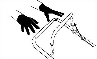
Testing Blade/Engine Control Lever
2. Release blade/engine control lever.
3. Listen for blade and engine to stop.
Starting Engine
Run engine only in a ventilated area. If engine is run in an enclosed area, open doors to bring in outside air. |
IMPORTANT: Avoid damage! To help prevent damage to recoil starter and band brake, do not start engine: |
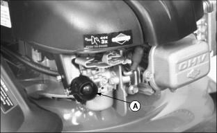
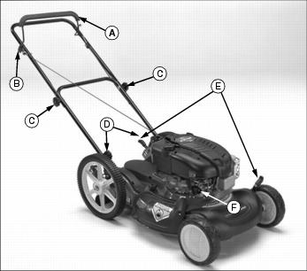
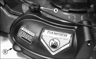
1. Prime engine by pressing primer bulb (A):
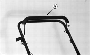
2. Hold blade control lever (B) against handle.
· Engine and blade will stop if blade control lever is released.
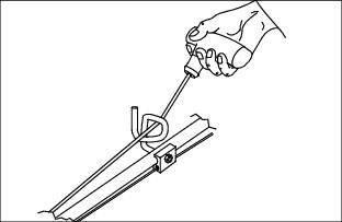
3. Pull starter handle until you feel resistance, then pull fast and steady.
4. Return rope slowly after engine starts.
Stopping Engine
Release handle and levers.
Using Side Discharge Chute
1. Release blade control lever to stop engine.
2. Remove mulch guard knob (A) from threaded stud.
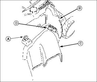
3. Lift and hold spring loaded mulch guard (B) up.
4. Install side discharge chute (C) under much guard spring and mounting bracket (D) and lower onto threaded stud.