Introduction
Product Identification
Safety
Operating
Replacement Parts
Service Intervals
Service Lubrication
Service Engine
Service Transmission
Service Electrical
Removing and Installing Battery
Checking Battery Electrolyte Level
Replacing Instrument Panel Bulbs
Service Miscellaneous
Troubleshooting
Storage
Assembly
Specifications
Warranty
John Deere Quality Statement
Service Record
Copyright© Deere & Company

Service Electrical
Battery
Removing and Installing Battery
· Wear eye protection and gloves. · Do not allow direct metal contact across battery posts. |
Removing
1. Park the vehicle safely. (See Parking Safely in the SAFETY section.)
· 4x2 - Raise and secure cargo box. Raise passenger seat.
· 6x4 - Access through opening at rear of vehicle.
Picture Note: GATOR 6x4 shown.
3. Disconnect all black negative cables (A) from battery first.
4. Slide back rubber protective cover (B) and disconnect all red positive cables.
5. Disconnect rubber hold-down strap (C).
6. Release latches on air cleaner canister cover (D). Remove cover to provide clearance for battery removal.
NOTE: If your battery is equipped with rubber vent hose, be sure hose does not detach from vent cap when removing battery.
IMPORTANT: Avoid damage! Dirt and debris can enter engine when air cleaner canister is opened. Install cover immediately after removing battery to keep contamination to a minimum. |
8. Install air cleaner canister cover with rubber dust unloading valve pointing downward. Check instruction molded into canister cover for proper installation.
Installing
1. Release latches on air cleaner canister cover. Remove cover to provide clearance for battery installation.
NOTE: If your battery is equipped with rubber vent hose, make sure vent cap is installed so hose is on negative (-) side of battery for 4x2 or positive (+) side of battery for 6x4.
2. Install battery into vehicle with negative (-) terminal positioned toward rear of vehicle.
3. Install air cleaner canister cover with rubber unloading valve pointing downward. Check instruction molded into canister cover for proper installation.
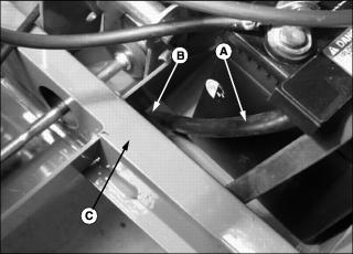
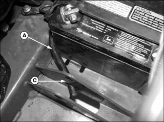
4. If equipped, route rubber vent hose (A):
· 4x2 - Route hose through drain hole (B) in frame or over back side of frame rail (C). Make sure hose does not extend too far below vehicle where it could be pulled off by ground debris.
· 6x4 - Route hose through lower hole in power lift cylinder plate (C).
5. Install battery hold-down strap.
6. Connect all red positive cables to positive (+) battery terminal first. Tighten the connections.
7. Connect all black negative cables to negative (-) battery terminal. Tighten the connections.
8. Apply petroleum jelly to battery terminals to help prevent corrosion.
9. Slide protective cover down the battery positive cable and seat it over the positive (+) terminal.
Checking Battery Electrolyte Level
1. Park the vehicle safely. (See Parking Safely in the SAFETY section.)
2. Remove battery from vehicle and set it on a level surface.
3. Remove battery cell caps. Make sure cap vents are not plugged.
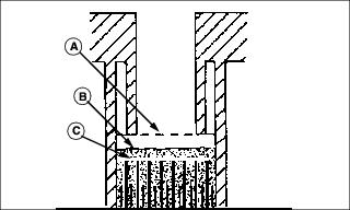
IMPORTANT: Avoid damage! Do not fill cells to the bottom of filler neck (A). Electrolyte can overflow when battery is charged and cause damage. |
4. Electrolyte (B) should be approximately halfway between bottom of filler neck (A) and top of plates (C).
5. Add distilled water if necessary.
Clean Battery and Terminals
· Wear eye protection and gloves. · Do not allow direct metal contact across battery posts. |
1. Remove battery from vehicle.
2. Wash battery with solution of four tablespoons of baking soda to one gallon of water. Be careful not to get the soda solution into the cells.
3. Rinse the battery with plain water and dry.
4. Clean terminals and battery cable ends with wire brush until bright.
5. Apply petroleum jelly or silicone spray to terminals to prevent corrosion.
Using Booster Battery
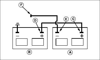
1. Connect positive (+) booster cable to booster battery (A) positive (+) post (C).
2. Connect the other end of positive (+) booster cable to the disabled vehicle battery (B) positive (+) post (D).
3. Connect negative (-) booster cable to booster battery negative (-) post (E).
4. Connect the other end (F) of negative (-) booster cable to a metal part of the disabled machine frame away from battery.
5. Start the engine of the disabled machine and run machine for several minutes.
6. Carefully disconnect the booster cables in the exact reverse order: negative cable first and then the positive cable.
Replacing Headlight Bulb
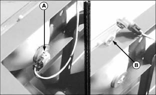
2. Rotate bulb socket (A) 1/3 of a turn and remove socket from housing.
IMPORTANT: Avoid damage! Do not touch glass portion of new bulb with bare skin. Contact with oils or dirt will reduce bulb life. Handle bulb by the base or with a clean cloth or gloves. |
3. Install new bulb (B) into socket, and install socket into housing.
IMPORTANT: Avoid damage! Vibration of hood against headlight housing may cause headlight lamps to fail early. Allow clearance around headlight housings when installing hood. |
Replacing Headlight Housing
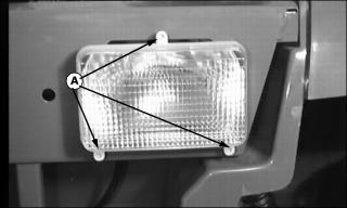
2. Disconnect bulb socket from housing.
3. Remove screws (A) at back side of light.
4. Install new assembly and install screws.
IMPORTANT: Avoid damage! Vibration of hood against headlight housing may cause headlight lamps to fail early. Allow clearance around headlight housings when installing hood. |
Replacing Instrument Panel Bulbs
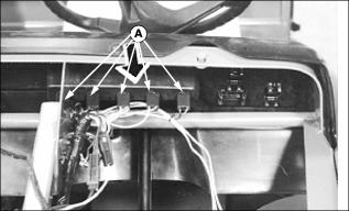
Picture Note: Hood shown removed for clarity. Removal of hood not required.
1. Reach under dash panel and remove appropriate bulb socket (A) from plastic housing.
· Rotate bulb socket 1/4 turn.
· Pull socket straight outward.
2. Remove bulb from socket. Discard bulb.
3. Install new bulb in socket.
4. Align and insert bulb socket into plastic housing. Turn socket 1/4 turn to lock in place.


