Introduction
Product Identification
Safety
Operating
Replacement Parts
Service Intervals
Service Lubrication
Service Engine
Service Transmission
Service Electrical
Service Miscellaneous
Troubleshooting
Storage
Assembly
Clean and Polish Plastic Hood and Fenders
Specifications
Warranty
John Deere Quality Statement
Service Record
Copyright© Deere & Company

Assembly
Prepare Vehicle For Assembly
1. Remove top and sides of shipping crate.
2. Remove seats and packaged parts from vehicle.
3. Remove tires from cargo box and sides of vehicle.
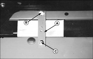
4. Locate two shipping brackets (A) on each side of vehicle frame.
5. Remove self-tapping screws (B) at each side. Retain these four screws to install the load guard later.
6. Lift cargo box off vehicle frame.
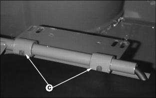
7. Remove self-tapping screws (C) and shipping brackets (A). Discard the shipping brackets.
8. Install two self-tapping screws (C) back into holes they were removed from on right side of machine. Install one of these screws into rear hole on left side of machine. Discard the last screw.
9. Remove and discard the shipping hardware securing the vehicle to pallet at foot platform and rear frame.
Remove Battery
· 4x2 - Access under passenger seat.
· 6x4 - Access through opening at rear of vehicle.
Picture Note: GATOR 6x4 shown.
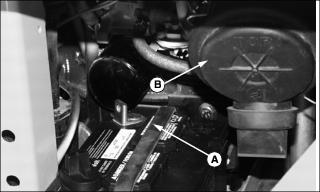
2. Disconnect rubber hold-down strap (A).
3. Release latches on air cleaner canister cover (B). Remove cover to provide clearance for battery removal.
4. Remove battery from vehicle. Remove and discard the protective cap from the negative (-) terminal.
5. Install air cleaner cover with rubber dust unloading valve pointing downward. Check instruction molded into canister cover for proper installation.
Check Battery Voltage
Battery is filled with acid and charged when it left the factory. To extend battery life, check voltage prior to delivery. Fully charge the battery if voltage is less than 12.6 volts.
Reduce Tire Pressure
2. Check all tires with an accurate gauge. Reduce pressure to 34 - 41 kPa (5 - 6 psi).
Install Wheels
Install Rear Wheels
1. Measure circumference of rear tires. Select the wheels with largest tire circumference for the most rearward position to provide the best ground contact for drive wheels.
2. Install plastic cap on each rear axle hub.
3. Raise rear of vehicle with a safe lifting device. Place support stands under vehicle.
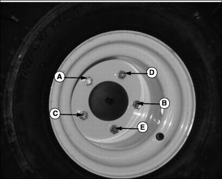
4. Attach each rear wheel to axle hub with valve stem to outside using five wheel bolts. Tighten wheel bolts evenly in proper sequence (A), (B), (C), (D), and (E) until snug. Finish tightening to 90 N·m (65 lb-ft) using a torque wrench.
5. Remove support stands and lower vehicle.
Install Front Wheels
1. Raise front of vehicle with a safe lifting device. Place support stands under vehicle.
2. Slide front wheels onto front axle hubs.
3. Secure front wheels with M16x40 flanged cap screws. Tighten cap screws to 90 N·m (65 lb-ft) using torque wrench.
4. Remove safety stands and lower vehicle to the ground.
Install Spark Arrestor (4x2)
NOTE: Spark arrestor is factory-installed on 6x4 utility vehicles.
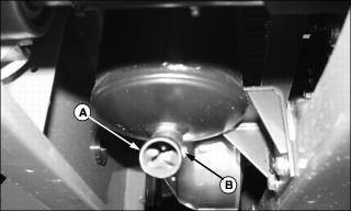
1. Align hole in spark arrestor (A) with pre-drilled hole in muffler pipe.
2. Slide screen end of arrestor into muffler pipe.
3. Install and tighten tap screw (B) to secure.
Install Steering Wheel
1. Remove and discard plastic protective cap from steering shaft.
2. Install steering wheel onto steering shaft. Turn steering wheel to position front wheels straight and facing forward.
4. Apply multi-purpose grease to steering shaft.
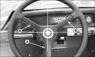
5. Install steering wheel onto steering shaft with one spindle (A) positioned at 180° at bottom of wheel and spindles (B) at approximately 45° at top of wheel.
6. Position front wheels straight and facing forward.
7. Install steering wheel onto steering shaft.
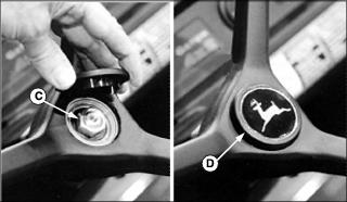
8. Install nut (C) and tighten until snug.
9. Install logo cap (D) so leaping deer is positioned properly.
Install Seats
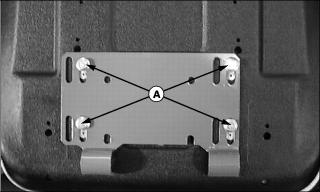
1. Remove screws (A) from bottom of seat base bracket on each seat.
NOTE: Apply silicone lubricant to inner surface of seat bushings to improve ease of seat rotation if desired.
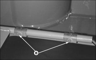
2. Install rubber seat bushings (B) onto support rail so tabs face toward rear of vehicle.
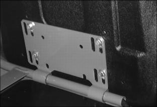
3. Position seat base bracket onto support rail so hinges (C) fit around rubber bushing tabs.
NOTE: Seat hardware must be installed in correct slots in bracket. Always use set of slots closest to center of vehicle when installing seat.
4. Rotate seat bracket upward. Install original hardware in slots closest to center of vehicle to secure seat. Do not tighten completely.
5. Slide seat forward or rearward to desired position.
6. Tighten seat screws to 10 N·m (7 lb-ft).
Install Battery
Picture Note: GATOR 6x4 shown.
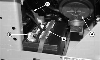
1. Remove air cleaner canister cover (A) to provide clearance for battery installation.
2. Install battery into vehicle with negative (-) terminal (B) positioned toward rear of vehicle.
3. Install air cleaner canister cover with rubber dust unloading valve pointing downward. Check instruction molded into canister cover for proper installation.
4. Secure battery hold-down strap (C).
5. Install red positive battery cable (D) to positive (+) terminal first using M6x16 cap screw, flat washer, and nut. Tighten the connection.
6. Install black negative battery cable to negative (-) terminal last using M6x16 cap screw, flat washer, and nut. Tighten the connection.
7. Apply petroleum jelly on battery terminals to help prevent corrosion.
8. Slide protective cover down the battery positive cable and seat it over the positive (+) terminal.
Install Cargo Box
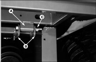
1. Position cargo box onto vehicle frame so hinges (A) are positioned inside pivot brackets (B).
2. Secure cargo box using M12x90 cap screws and flanged lock nuts (C). Install cap screw with threads to the outside of vehicle.
3. Tighten cap screws until pivot brackets contact ends of hinge.
4. Apply a spray lubricant to the pivot hardware, hinges, and pivot brackets.
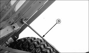
NOTE: The 90° bent end of support rod is already installed in cargo box frame.
5. Raise and hold cargo box securely. Cut tie strap to release cargo box support rod (D).
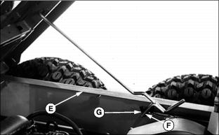
6. Push inward on support rod forcing it over sill (E).
7. Route end (F) of support rod into slot (G).
Install Load Guard
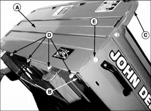
1. Install load guard (A) to cargo box so bottom lip (B) is positioned on underside of box and square tube frame (C) is to the inside of box.
2. Secure bottom of load guard with M8x20 carriage bolts, flat washers, and flanged lock nuts (D). Tighten nuts to 25 N·m (18 lb-ft).
3. Attach both sides of load guard using self-tapping screws (E) retained from shipping brackets on cargo box.
Remove Shipping Wrap
1. Remove screws (A) and lift hood up and off vehicle.
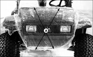
2. Remove plastic shipping wrap from hood.
3. Use a sharp utility knife to carefully cut the plastic wrap where fenders join metal frame.
4. Pull plastic wrap up and away from fender and remove remaining plastic in joint by pulling from below.
5. Remove the plastic wrap from rear fenders and box extensions.
IMPORTANT: Avoid damage! Vibration of hood against headlight housing may cause early failure of headlight lamps. Allow clearance around headlight housings when installing hood. |
6. Install hood and tighten top screws first.
7. Push hood upward leaving space around headlight housings. Tighten bottom screws.
Lubricate Front King Pins
NOTE: Refer to Service Lubrication section of operator's manual for recommended lubricants.
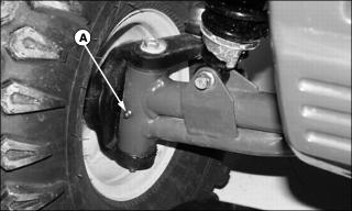
1. Lubricate grease fitting (A) on each king pin bushing with one or two shots of recommended grease.
2. Wipe off excess grease from fitting.
Check Fluid Levels
NOTE: Refer to the Service sections of the operator's manual for information concerning check locations and proper fluid levels.
1. Check engine coolant level (GATOR 6x4).
Clean and Polish Plastic Hood and Fenders
1. Remove any dust or dirt with water.
2. Dry thoroughly to avoid water spots.
3. Spray PLEDGE® onto plastic surfaces and leave on for 30 to 60 seconds. (PLEDGE® is a Registered Trademark of S.C. Johnson, Co.)

