![]()
Introduction
Product Identification
Safety
Operating
Rear Wheel Spacing (Two Wheel Steer Models With 23 x 10.50-12 Tires)
Using The Reverse Implement Option
Using Hydraulic Control Levers
Using Engine Air Restriction Indicator (Optional Equipment)
Installing Rear Wheel Weights (Two-Wheel Steer Tractors)
Installing Rear Wheel Weights (All-Wheel Steer Tractors)
Replacement Parts
Service Interval Chart
Service Lubrication
Service Engine
Service Transmission
Service Electrical
Service Miscellaneous
Troubleshooting
Storing Machine
Assembly
Specifications
Warranty
John Deere Quality Statement
Service Record
Copyright© Deere & Company

Operating
Daily Operating Checklist
o Check Air Restriction Indicator (if so equipped).
o Remove grass and debris from machine.
Dash Controls

H - Tilt Steering Wheel Button

Foot/Platform Controls

Miscellaneous Controls
Free Wheeling Lever

Air Restriction Indicator

A - Air Restriction Indicator (Optional)
Adjusting Steering Wheel
NOTE: Steering wheel has four tilt positions.

1. Push in button (A) and push or pull wheel to a comfortable operating position.
NOTE: Before operating, be sure steering wheel is locked in position.
Adjusting Seat (425)
Adjust Forward / Rearward
NOTE: This tractor is equipped with a fourteen position slide rail seat. Be sure seat is locked in position before operating.

1. Push lever (A) to the left.
2. Slide seat forward or backward to desired position.
Adjust Seat Suspension
NOTE: Seat suspension can be adjusted to better match the weight of the operator.
2. Suspension coils can be moved to three different settings:
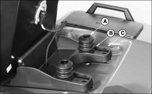
3. Make sure suspension coils are in the same ride setting for each side.
Adjusting Seat (445)
NOTE: This tractor is equipped with a fourteen position slide rail seat. Be sure seat is locked in position before operating.

1. Push lever (A) to the left.
2. Slide seat forward or backward to desired position.
Rear Wheel Spacing (Two Wheel Steer Models With 23 x 10.50-12 Tires)
IMPORTANT: Avoid damage! On 26 x 12.00-12 tire option, wheels should always be in the wide position. |
1. Park tractor on level surface. STOP engine. LOCK park brake. Put blocks in front and back of front wheels.

2. Loosen five rear wheel bolts (A). Lift rear wheels off the ground with floor jack or hoist.
· Turf tires: Install wheel on same side of tractor with valve stem inside.

· Bar tires: Install each wheel on opposite side of tractor. Bars on tires must point forward.
· Tighten wheel bolts to 88 N·lm (65 lb-ft).
· Lower rear wheels to the ground. Remove blocks from front wheels.
Testing Safety Systems
Use the following checkout procedure to check for normal operation of tractor.
If there is a malfunction during one of these procedures, DO NOT operate tractor. (See your John Deere dealer for service.)
Perform these tests in a clear open area. Keep bystanders away.
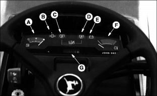
Test 1
Check operation of indicator lights:

· LOOK: Indicator lights (A) and (B) must light.
· LOOK: On Model 445, indicator light (C) will come on and go out in two to three seconds.
· If one indicator does not light, see Replacing Indicator Light Bulb in Service-Electrical section.
· If new indicator bulb does not light or no indicators work, see your John Deere dealer.
Test 2
1. Unlock park brake and release brake pedal.
2. Turn key to START position.
Test 3
1. Depress brake pedal, or lock park brake.
2. Put PTO switch lever in ON position.
3. Turn key to START position.
Test 4
· Start engine. Run engine at MAXIMUM engine speed. Unlock park brake and release brake pedal.
· Put PTO switch lever in ON position.
· Raise up off seat. DO NOT get off tractor.
· Engine should begin to die. PTO should immediately SHUT OFF and mower blades should STOP.
· Raise up off seat. DO NOT get off tractor.
· Raise up off seat. DO NOT get off tractor.
· Engine should continue to run.
Test 5
NOTE: This test should be performed once a year or every 100 hours.
Perform this test while sitting on the tractor.

3. Watch left-hand side mower spindle (A). DISENGAGE PTO, mower spindle should stop turning within 5 seconds.
4. If spindle does not stop within 5 seconds, the PTO brake needs servicing. (See your John Deere dealer for service.)
Test 6
Test Reverse Implement Option:
2. Engage PTO to start attachment.
3. Look behind the vehicle to be sure there are no bystanders.
4. Begin REVERSE travel by depressing REVERSE foot pedal.
5. Attachment should stop operation. If attachment continues to operate while tractor travels in REVERSE, do not continue to operate attachment. See your John Deere dealer for service.
Using the Park Brake
Lock Park Brake:
Always LOCK park brake before getting off tractor or leaving tractor unattended. |

1. Push down on brake pedal (A) and hold pedal all the way down.
2. Pull park brake lever (B) up to LOCK park brake.
3. Release pedal and then park brake lever. Pedal should stay down and park brake lever should stay up in LOCKED position.
Unlock Park Brake:
1. Push down on brake pedal and hold pedal all the way down.
2. Push park brake lever down.
3. Release pedal. Pedal should come up to operating position.
Indicator Lights and Gauges

Starting the Engine
NOTE: You must hold brake pedal down, or LOCK park brake, before you can start the engine. Be sure PTO switch is off.
1. LOCK park brake or depress brake pedal.

2. Push throttle lever (A) up to 1/2 position.
NOTE: You may not need to choke a warm engine.
3. Model 425: COLD engine: Choke engine by pushing choke lever (B) all the way up to CHOKE (Closed) position.

4. Turn key (A) to the RUN position (C).

· Oil Pressure indicator (E) will be ON.
IMPORTANT: Avoid damage! If indicator (F) blinks after engine is started, STOP engine. Be sure to wait 1/2 second before cranking engine again. |
· Battery Discharge indicator (G) will be ON.
· Model 425: Injection System Failure Indicator (F) will come on for a few seconds. WAIT for approximately 1/2 second before cranking the engine.
6. Turn key to the START position (D):
· If engine does not start within 5 seconds, turn key to STOP position (B) and wait 10 seconds.
· Crank engine again for 5 seconds.
Repeat this procedure if necessary.
7. As soon as engine starts, release key. The key will return to the RUN position and all indicator lights should be off. If a light does not go off, stop engine and perform appropriate service.
· After engine starts, gradually pull the choke lever back to the HALF-WAY position. You may have to leave the choke lever at this position until the engine runs smoothly.

· When engine is running smoothly, gradually pull choke lever down to the NO CHOKE (Open) position (A).
Stopping the Engine

2. Pull throttle lever (A) down to the SLOW position.
IMPORTANT: Avoid damage! To avoid fuel pump damage, be sure key is in STOP (Off) position whenever engine is not running. |
NOTE: Model 425: Engine may run for a second after key is turned off to burn unused fuel in the system.
3. Turn key (B) to STOP (Off) position.
4. LOCK park brake and remove key.
Using Travel Controls
· Before moving forward or rearward, make sure area is clear of bystanders, especially children. |
TO TRAVEL FORWARD:

· Slowly push down forward pedal (B). Tractor will travel faster the farther down you push the pedal.
· Release forward pedal, tractor will automatically return to neutral and STOP.
TO TRAVEL IN REVERSE:
NOTE: Any operating attachment will stop as the REVERSE foot pedal is depressed with attachment engaged.
1. Bring the vehicle to a stop.
2. Push PTO knob down to the OFF position to disengage attachment.
3. Look behind the vehicle to be sure there are no bystanders nearby.
4. Slowly push down reverse pedal (C). Tractor will travel faster the farther down you push the pedal. Release reverse pedal, tractor will automatically return to neutral and STOP.
· Release either travel pedal, tractor will automatically return to neutral and STOP.
· Push down on brake pedal (A). Tractor brakes will be applied to assist in stopping.
Using Cruise Control
Use cruise control when you want to maintain travel speed without having to hold the forward travel pedal down. Cruise control operates only for forward travel.
Operate tractor in a large, open area to learn how the cruise control works.
Engage Cruise Control
1. Push forward pedal down until you reach desired travel speed.

2. Pull lever (A) up to lock the cruise control.
Disengage Cruise Control
Using The Reverse Implement Option
· Before moving forward or rearward, make sure area is clear of bystanders, especially children. |
NOTE: Operating the mower while backing up is strongly discouraged. The Reverse Implement Option should be used ONLY when operating another attachment or when the operator deems it necessary to reposition the machine with the mower engaged.
1. Stop the machine FORWARD travel with attachment engaged.
2. Look behind the vehicle to be sure there are no bystanders.

3. Lift and hold the PTO knob (A) up past the PTO engagement position to activate the reverse implement position while depressing REVERSE foot pedal slightly.
NOTE: If the attachment stops while repositioning the machine, return PTO knob to the OFF position. Begin again with Step 2 in procedure.
4. As the machine begins to move backward, release the PTO knob and reposition the machine.
5. Resume FORWARD travel. The attachment should continue operating.
6. Repeat Steps 1 through 5 to reposition the machine again.
Using Differential Lock
IMPORTANT: Avoid damage! To prevent damage to differential, DO NOT engage differential lock at high speeds. |
The differential lock is used to provide better traction when rear wheels start to slip. Do not use differential lock unless you are experiencing rear wheel slippage. Engaging differential lock will cause both rear wheels to drive equally to improve traction.
Engage Differential Lock

2. Push down on differential lock pedal (A). Lock will remain engaged as long as there is rear wheel slippage or pedal is depressed.
NOTE: Turning radius is increased when differential is locked.
When brake pedal is depressed, differential lock will automatically engage.
Disengage Differential Lock
1. Release differential lock pedal. Differential lock will disengage when rear wheels are no longer slipping.
Using Hydraulic Control Levers
Using Hydraulic Valve
NOTE: Only tractors equipped with the optional front hitch or loader will be equipped with a hydraulic valve.
Hydraulic control levers operate differently depending on the attachment. When using an attachment other than a mower deck, please see the ATTACHMENT OPERATOR'S MANUAL.

· When operating mower deck or rear implement lift - turn T-handle (A) counterclockwise until tight.
· When operating front hitch/attachments - turn T-handle (A) clockwise until it is bottomed out.
Using Control Levers
Using control lever (B) with a mower deck:

· Pull and hold lever back until mower deck is raised.
· Push lever forward to lower the mower deck.

· This control lever is used to raise and lower other attachments such as a snowthrower, rotary broom, etc.
NOTE: If you are not using lever (C), periodically move lever back and forth to maintain lubrication. Be sure lever is returned to the middle (NEUTRAL) position and not locked in the forward (FLOAT) position.
Using PTO (Power Take-Off)
NOTE: Any operating attachment will stop as the REVERSE foot pedal is depressed with attachment engaged. Prior to operating the PTO, see Reverse Implement Option in this section.
This tractor is equipped with a 2000 rpm mid PTO.
Engage PTO
1. Reduce travel speed or stop tractor.

2. After engine has warmed, push throttle lever (B) all the way up to maximum engine speed position.
3. Pull PTO knob (A) up. PTO indicator light (C) will come on when PTO is engaged.
NOTE: Always operate engine at maximum speed when PTO is engaged.
Disengage PTO
1. Push knob down to disengage PTO. PTO indicator light will go out.
NOTE: If brake pedal is depressed, PTO will disengage.
Using Mower Height Control
IMPORTANT: Avoid damage! Use this procedure to determine cut height. Do not use hydraulic control levers to determine cut height. |
1. Park tractor on a hard, level surface.

2. Pull back hydraulic control lever (A) and raise mower as high as it will go.

4. Flip open crank handle (B). Crank height control counterclockwise far enough to permit mower to be lowered to surface. Do not turn lever too far, height control may be damaged.
NOTE: NOTE: One full rotation of height control equals approximately 12.5 mm (1/2 in.) of height adjustment.
5. Lower mower to desired cutting height with hydraulic control lever.
6. Crank height control clockwise until it is tight to lock mower in set cutting height. Close crank.
7. To LOCK mower in completely raised position:
· Raise mower as high as it will go using the hydraulic control lever.
· Crank height control clockwise until it is tight. Close crank.
Mower Lift Arms
Using Free-Wheeling Lever
IMPORTANT: Avoid damage! To prevent transaxle damage, NEVER tow the tractor. Only push tractor by hand. Do not use another vehicle to push tractor. |
When you need to move the tractor without starting the engine, use the free-wheeling lever:

· Pull free-wheeling control lever (A) up.
· Push tractor to desired location.
Lever will return to the operating position when tractor is started and driven.
Using Engine Air Restriction Indicator (Optional Equipment)
This tractor can be equipped with an air restriction indicator. The indicator is designed to inform you when it is time to service the air filter elements.

The air restriction indicator (A) is numbered to measure air restriction. As the filter collects more dirt, the restriction increases, raising the numbered reading on the indicator.
Using Weights And Tire Chains
Front Weights
There are two types of front weights available for your tractor, suitcase weights and wheel weights. Suitcase weights can be mounted on the front bumper and wheel weights are mounted to the front wheels.
Five suitcase weights can be mounted on the front bumper. An additional four weights can be added if you have installed a "Front Weight Bracket Kit." Each suitcase weight weighs 19 kg (42 lbs).
NOTE: Before installing wheel weights on your tractor, MAKE SURE that the tire valve stems are facing to the inside.
A front wheel weight weighs 16 kg (35 lbs). Two front wheel weights and mounting kit are required.
See your John Deere dealer for kits and weights to best fit your needs.
Rear Weights
There are two types of rear weights available for your tractor, suitcase weights and rear wheel weights. The suitcase weights are mounted on a bracket on the back of the tractor and wheel weights are mounted to the rear wheels.
To use rear suitcase weights, you need to order the "Rear Weight Bracket Kit". The rear weight bracket holds up to six 19 kg (42 lb) suitcase weights. Use of these weights is required when an attachment, such as snowthrower or snowblower is used.
To use rear wheel weights, you need to order the appropriate weight and in some cases the hardware to attach the weights.
See your John Deere dealer for kits and weights to best fit your needs.
If you are installing rear wheel weights, please use the following instructions.
Installing Rear Wheel Weights (Two-Wheel Steer Tractors)
23x10.50-12 Tires With BM17976 Weight
BM17976 is a 23 kg (50 lb) plastic coated weight and includes the necessary hardware.

· Measurement (A) should be 160 mm (6.3 in.).
23x10.50-12 Tires With BM17972 Weight
BM17972 is a 23 kg (50 lb) Weight. You must also order BM18089 attaching hardware when using one weight and BM17977 attaching hardware when using two weights.

· Measurement (C) should be 200 mm (7.9 in.).
26x12.00-12 Tires With BM17976 Weight
BM17976 is a 23 kg (50 lb) plastic coated weight and includes the necessary hardware.

· Measurement (A) should be 210 mm (8.3 in.).
26x12.00-12 Tires With BM17972 Weight
BM17972 is a 23 kg (50 lb) Weight. You must also order BM17977 attaching hardware when using one weight and BM18101 attaching hardware when using two weights.

· Measurement (C) should be 195 mm (7.7 in.).
· Measurement (D) should be 250 mm (9.8 in.).
26x12.00-12 Tires With BM17973 Weight
BM17973 is a 33 kg (72 lb) Weight. You must also order BM18089 attaching hardware.

26x12.00-12 Tires With BM17973 Weight and BM17972 Weight
BM17973 is a 33 kg (72 lb) Weight.
BM17972 is a 23 kg (50 lb) Weight.
You must also order BM17977 attaching hardware when using one BM17973 and one BM17972 weight. Order BM18101 attaching hardware when using one BM17973 and two BM17972 weights.

A - One BM17973 weight and one BM17972 weight
B - One BM17973 weight and two BM17972 weights
· Measurement (C) should be 200 mm (7.9 in.).
· Measurement (D) should be 260 mm (10.2 in.).
Installing Rear Wheel Weights (All-Wheel Steer Tractors)
IMPORTANT: Avoid damage! To avoid damage to axle, be sure to install weight mounting hardware as shown. |
23x10.50-12 Tires With BM17972 Weight
BM17972 is a 23 kg (50 lb) Weight. You must also order BM18094 attaching hardware when using one weight and BM18089 attaching hardware when using two weights.

Install weight(s) as shown. Cut off any excess threads on bolts.
23x8.50-12 Tires With BM17972 Weight
BM17972 is a 23 kg (50 lb) Weight. You must also order BM18094 attaching hardware when using one weight and BM18089 attaching hardware when using two weights.

Install weight(s) as shown. Cut off any excess threads on bolts.
Using Tire Chains
Tire chains are recommended for use with a snowthrower and, under certain conditions; the front blade. (See your John Deere dealer for tire chains).
Installing the Chains
1. Park the tractor on a level surface.
5. Remove chains from bag and lay out flat with the cross chain hook ends facing upward. Remove any twists and tangles from cross chain and rim chain.

6. Drape chain over tire with the lever fastener on outside of tire and cross link hooks (A) facing upward and away from tire.
7. Adjust chain for straightness and an even amount of cross chain links on each side of tire.
8. Place the first cross chain (opposite the end with fastener and inside hook) under tire.

9. Pull the inside rim chain tight and hook the inside hook. Pull the outside rim chain tight and hook the outside lever fastener (B) by running the end through a free link (C). Close the fastener by rotating it back 180 degrees and engaging the hook (D) on the end of the fastener into a rim chain link (E). Make sure the chain is centered on the tire with approximately the same number of free rim links (F) on the inside and outside.


10. Tie excess rim chain links (G) back to the rim chain.
11. The chain should be as tight as possible by hand. Unhook the fastener and repeat Step 5 if the chain is loose.
12. Drive forward on chains 30' - 40' and recheck for tightness. Adjust as necessary.
Transporting Tractor

Use a heavy-duty trailer to transport your tractor.
Drive tractor forward onto a trailer. Lower any attachments to trailer deck.
Fasten tractor to trailer with heavy-duty straps, chains, or cables. Both front and rear straps must be directed down and outward from tractor.
Trailer must have signs and lights required by law.
Mowing Tips
Before mowing, be sure deck is leveled and mower wheels are in the proper position.
When you mow an area for the first time, travel SLOW and cut HIGH so you can:
· Learn the best mowing pattern.
· Help prevent hitting objects hidden in the grass.
Mow grass only when it is dry: Wet grass may plug mower and leave a trail of grass clumps.
Mow grass often: Short grass clippings will decay quickly.
Mow at full throttle for best performance.
Use travel speed that fits conditions:
· Travel SLOW when you mow thick, tall grass.
· FAST travel or sharp turns may produce stripes or uneven cut: slow down.
· Travel at MODERATE speed when you mow a thin stand of grass.
Mow often enough so you cut only 1/3 of grass blade in one mowing. Cutting grass too short may kill grass and let weeds grow easily.
See your John Deere dealer for blades that will best fit your mowing conditions.
Aerate lawn to help stimulate soil organisms and root growth.
Trimming Tips
· Turn to left around trees, bushes, etc.
· Drive slowly. Avoid hitting trees, bushes, etc.
· If ground slopes up to a tree or bush, you may have to approach the tree or bush straight-on to avoid scalping.
To Avoid Scalping
· Pay attention to the way you drive: you can eliminate scalping.
· If mower scalps easily, cutting height may be too low for ground conditions-especially on lawns with many small mounds and ridges.
· Rear gauge wheels must be adjusted correctly.
· Drive over ridges and through shallow ditches straight-on, not at an angle.
Keep blades sharp: Dull blades will tear grass; tips of grass will then turn brown.
Check lawn regularly for uneven cut. If cut is uneven:
· LOOK: Mower may not be level.
· Slow down before you make a turn.
Use thatcher (available from John Deere dealer) in late spring or summer to pull up dead grass and aerate ground.
For bagging information, see your Bagger Operator's Manual.
After Mowing
· Let engine cool-to prevent fire when you store mower.
· Clean top of deck, engine, and chute with compressed air, if possible-to help prevent buildup and fire.
· Clean under deck with water under pressure-to prevent buildup and remove corrosive lawn chemicals.
Bagging Tips
For best performance, bagger needs good airflow. To help increase airflow:
· Keep underside of deck and chute clean.
· Clean bag(s) often with water from garden hose, from outside to inside of bag. Let bag(s) dry before use.
LOOK: Check level of clippings in bags often. When bag(s) are full:
· Mower may leave a trail of clippings.
Bagging and Composting
Many communities will no longer haul lawn clippings and leaves to landfills. Bagging and composting clippings and leaves is one way to solve this problem.
Clippings from grass bag may also be used as mulch, or sheet compost, between garden rows and around trees and shrubs. This mulch will:
· Add nutrients to soil as it decays.
· Help keep soil temperature down during hot weather.
You may compost clippings and leaves in various ways. See garden magazines or clubs for information, or go to your local library for help.
Finished compost is crumbly. It is rich in soil nutrients, and can be spread on your lawn. Compost may also be worked into soil. It adds humus to soil and improves soil texture, making soil looser and easier to work.
Mulching Tips
· You do not have to rake or bag grass or leaves.
· Lawn holds moisture better during dry weather.
· Soil temperatures stay down during hot weather.
· Mulch adds nutrients to soil, and reduces need for fertilizer.
Mulching does not make thatch. Frequent shallow watering and fertilizer application produce thatch from roots that grow close to surface.
Be careful when you mulch leaves in Fall. Grass needs sunlight in Fall to help store food for Winter. A thick layer of mulched leaves can prevent sunlight from getting to grass and smother it. You may have to mow with grass bag to remove this layer.
Mulch only when the grass and leaves are dry.
Mulching wet or damp grass or leaves may cause problems:
· Clippings and leaves may build up on the underside of the mower deck.
· Cut grass and leaves may form clumps.
· Clippings and leaves may not be cut into small bits.
· Engine may work harder and use more fuel.
Cut only top 1/3 of grass at a time.
Use a different mowing pattern each time you mow. Overlap mowing paths 50-100 mm (2-4 in.).
Slow down. Mulching takes more power.