![]()
Introduction
Product Identification
Safety
Operating
Replacement Parts
Service Interval Chart
Service Lubrication
Service Engine
Engine Warranty Maintenance Statement
Changing Engine Oil and Filter
Checking Air Restriction Indicator (Optional Equipment)
Cleaning Radiator Screen and Fins
Servicing Air Cleaner Elements
Relieving Fuel System Pressure (445)
Service Transmission
Service Electrical
Service Miscellaneous
Troubleshooting
Storing Machine
Assembly
Specifications
Warranty
John Deere Quality Statement
Service Record
Copyright© Deere & Company

Service Engine
Engine Warranty Maintenance Statement
Maintenance, repair, or replacement of the emission control devices and systems on this engine, which are being done at the customers expense, may be performed by any nonroad engine repair establishment or individual. Warranty repairs must be performed by an authorized John Deere dealer.
Adjusting Carburetor
NOTE: Carburetor is calibrated by the engine manufacturer and should not require any adjustments.
If engine is operated at altitudes above 1829 m (6,000 ft), some carburetors may require a special high altitude main jet. See your John Deere dealer.
Possible engine surging will occur at high rpm with no load (with transmission in "N" neutral and PTO switch in the OFF position. This is a normal condition due to the emission control system.
If engine is hard to start or runs rough, check the troubleshooting section of this manual.
After performing the checks in the troubleshooting section and your engine is still not performing correctly, contact your John Deere dealer.
Avoid Fumes
· If it is necessary to run an engine in an enclosed area, use an exhaust pipe extension to remove the fumes. |
Engine Oil
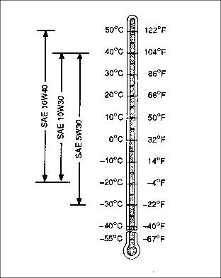
Use oil viscosity based on the expected air temperature range during the period between oil changes.
The following John Deere oil is preferred:
The following John Deere oils are also recommended if above preferred oil is not available:
· TORQ-GARD SUPREME® - SAE 5W30
Other oils may be used if all the above John Deere oils are not available and they meet one of the following:
· API Service Classification SH and SG
· CCMC Specifications G5 and G4
· Military Specification MIL-L-2104F
Arctic oils (such as SAE 0W30 or Military Specification MIL-L-46167B) may be used if temperatures fall below 30°C (22°F), but reduce the oil change interval by 50%.
1. Park vehicle on a level surface.
2. Check engine oil when oil is cold.
4. Remove dipstick (A). Wipe dipstick with a clean rag.
5. Install dipstick. Be sure dipstick is all the way down.
6. Remove dipstick. Check oil level on dipstick.
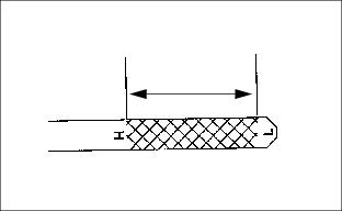
7. Oil level should be between FULL mark "H" and LOW mark "L" on dipstick.
8. If oil level is low, remove oil filler cap (B).
9. Add oil to bring oil level no higher than "H" mark on dipstick.
11. Install and tighten oil filler cap. Be sure cap is pushed all the way down.
Changing Engine Oil and Filter
1. Park vehicle on a level surface.
2. Run engine a few minutes to warm oil.
6. Remove right-hand side panel.
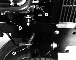
7. Route oil drain hose (C) to allow draining into oil pan.
8. Open drain valve (B) by turning it toward you.
NOTE: Be sure oil drain pan is under filter also.
9. Drain oil in pan. While oil is draining, change oil filter (A).
10. Remove filter using a filter wrench. Turn filter counterclockwise.
11. Apply a film of clean engine oil on seal of new filter.
12. Install filter. Turn filter until seal contacts mounting surface. Then turn filter BY HAND 1/2 turn more.
14. Return oil drain hose to inside of frame.
15. Install right-hand side panel.
16. Remove filler cap (B). Add approximately 1.4 L (1.5 qt) of oil.
17. Remove dipstick (A) to check oil level. Add oil only to FULL mark "H" on dipstick.
18. Install filler cap. Be sure cap is pushed all the way down.
19. Start engine and run at slow speed for two minutes. Check for leaks around filter and drain valve.
20. STOP engine. Check oil level.
21. Install dipstick. Lower hood.
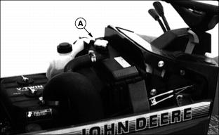
Cleaning Air Intake Screens
IMPORTANT: Avoid damage! Side panel intake screens must be clear of dirt and debris to prevent engine from overheating and to allow good air intake for air cleaner. |
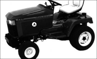
Clean air intake screens (A) on side panels using a brush or cloth.
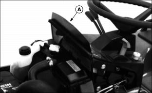
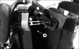
Checking Air Restriction Indicator (Optional Equipment)
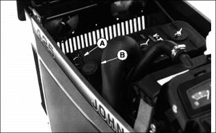
NOTE: Indicator will not signal correctly if indicator case has a break.
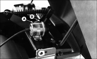
3. Check air restriction indicator: When yellow plunger (B) inside indicator reaches red line (A), air cleaner requires immediate service.
NOTE: Under normal operating conditions, it is not unusual to operate tractor for several hundred hours before indicator will show any restriction.
Cleaning Radiator Screen and Fins
3. Clean screen with a brush or compressed air.
4. Remove left-hand side panel.
5. Clean radiator cooling fins (B) using compressed air or water.
Servicing Air Cleaner Elements
IMPORTANT: Avoid damage! Only clean or replace air cleaner elements at interval recommended on service interval chart or when (optional) air restriction indicator reaches red line. |
2. Remove two wing nuts (A) and cover (B).
|
· DO NOT clean paper element, replace it. · DO NOT remove precleaner without first removing element away from carburetor. |
NOTE: Leave air intake hose attached to air cleaner cover.
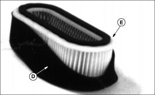
4. Check precleaner (D) for dirt and dust. If precleaner is dirty, remove it from paper element (E) and clean it as follows:
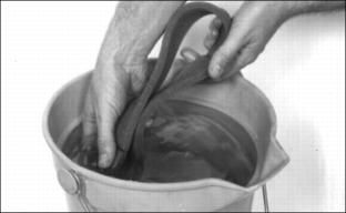
· Wash precleaner in warm, soapy water.
· Rinse precleaner in clean water.
· Squeeze precleaner to remove most of the water.
· Apply 30 mL (1 oz) of clean engine oil to precleaner.
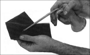
· Squeeze precleaner to distribute oil evenly and to remove excess oil.
5. Install precleaner on new element and install air cleaner.
6. Install air cleaner cover and wing nuts.
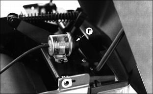
7. Push in button (F) to reset air restriction indicator if so equipped.
NOTE: Photo taken of machine equipped with an OPTIONAL Air Restriction Indicator.
9. Start engine and check indicator. Yellow plunger should be at or below the 178 mm (7 in.) mark.
Recommended Engine Coolant
The following John Deere coolant is preferred:
· COOL-GARD PRE-DILUTED SUMMER COOLANT (TY16036).
· COOL-GARD CONCENTRATED SUMMER COOLANT (TY16034)
If neither of the above coolants is available, use an ethylene glycol base coolant that meets the following specification:
Check container label before using to be sure it has the appropriate specifications for your machine. Use coolant with conditioner or add conditioner to coolant before using.
If using concentrate, mix approximately 50 percent antifreeze with 50 percent distilled or deionized water before adding to cooling system. This mixture will provide freeze protection to -37 degrees C (-34 degrees F).
Certain geographical areas may require lower temperature protection. See the label on your antifreeze container or consult your John Deere dealer to obtain the latest information and recommendations.
Engine Coolant Drain Interval
When using PRE-DILUTED DIESEL ENGINE ANTI-FREEZE/SUMMER COOLANT (TY16034) coolants, drain and flush the cooling system and refill with fresh coolant mixture every 60 months or 5,000 hours of operation, whichever comes first.
If above John Deere service coolants are not being used: drain, flush, and refill the cooling system with a fresh coolant mixture every 24 months or 600 hours of operation, whichever comes first.
Engine Coolant Drain Interval
When using John Deere Pre-Diluted (TY16036) Automobile and Light Duty Engine Service coolants, drain and flush the cooling system and refill with fresh coolant mixture every 36 months or 3,000 hours of operation, whichever comes first.
When using John Deere Concentrate (TY16034) Automobile and Light Duty Engine Service coolants, drain and flush the cooling system and refill with fresh coolant mixture every 24 months or 2,000 hours of operation, whichever comes first.
If above John Deere Automobile and Light Duty Engine Service coolants are not being used; drain, flush, and refill the cooling system according to instructions found on product container or in equipment Operator's Manual or Technical Manual.
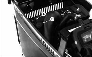
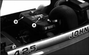
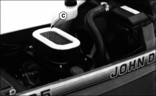
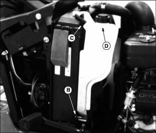
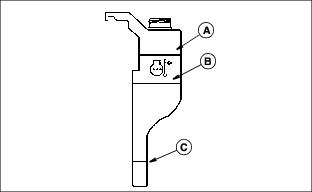
Checking Coolant Level
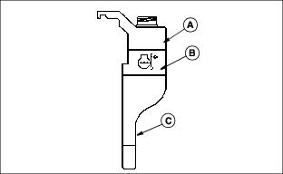
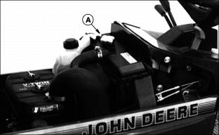
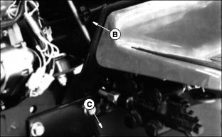
· If engine is warm (into green range on temperature gauge), coolant should be between lines (A) and (B) on coolant tank.
· If engine is cold, coolant should be above line (C).
Picture Note: Side panel removed for photo.
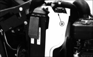
3. If coolant is low, remove coolant recovery tank cap (D). Add 50 percent ethylene glycol (without stop-leak additive) antifreeze and 50 percent water to the bring coolant up to the proper level.
4. Install and tighten coolant recovery tank cap.
5. Clean debris from side panel air intake screens and radiator screen.
6. Check condition of hoses. Check for leaks or loose connections.
Servicing Cooling System
Draining Cooling System
1. STOP engine. Let engine cool.
3. Slowly remove radiator cap (A).
4. Remove left-hand side panel.
5. Open radiator petcock (B). Drain coolant into a bucket (C).
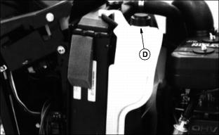
6. Remove right-hand side panel.
7. Remove black drain plug bolt (D) on each side of engine to drain coolant from engine block.
8. After all coolant has drained, close radiator petcock and install block drain plug bolts.
Flushing Cooling System
IMPORTANT: Avoid damage! To prevent engine damage, DO NOT pour water into a hot engine. DO NOT operate engine without coolant. |
1. Drain cooling system and fill with clean water and a cooling system cleaner recommended for aluminum engines. Follow the directions on the container.
2. Install and tighten radiator cap (A).
3. Start and run engine until it reaches operating temperature.
5. Drain cooling system immediately before rust and dirt settle.
· Pull overflow hose (C) from tank.
10. Install overflow hose to the bottom of the tank. Be sure hose is not kinked.
Filling Cooling System
When operating engine in extremely cold temperatures, see your John Deere dealer.
1. Check condition of coolant system hoses.
2. Install new hoses, if necessary.
3. Mix approximately 50% antifreeze with 50% distilled or deionized water.
5. Install and tighten radiator cap.
6. Run engine until needle on temperature gauge reaches the green range.
8. Coolant level should be between lines (A) and (B) on coolant tank. After engine cools, level should be above line (C).
9. Remove cap (D) to add coolant if necessary.
10. Tighten hose clamps, if necessary.
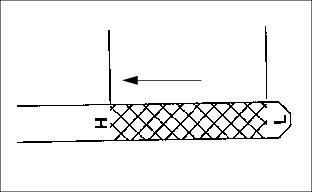
Replacing Fuel Filter (425)

2. Squeeze hose clamps (A) to disconnect fuel hoses from fuel filter (B).
NOTE: Install filter so arrow is pointing in the direction of fuel flow.
3. Connect hoses to new filter.
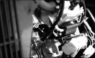
Relieving Fuel System Pressure (445)
2. Partially open fuel tank cap to relieve the pressure in the fuel tank. Tighten fuel tank cap.
4. Remove right-hand side panel.

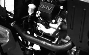
Picture Note: Model 445 (muffler shield removed)
5. Turn relief bolt (A) 1/2 turn counterclockwise to relieve pressure.
Replacing Fuel Filter (445)
IMPORTANT: Avoid damage! Before servicing any part of the fuel system, be sure to relieve pressure. For any service other than replacing the fuel filter, we recommend you see your John Deere dealer. |
2. Relieve fuel system pressure.
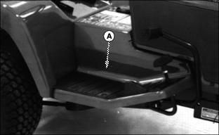
3. Reach under platform (A) and squeeze two clips (B) to disconnect fuel lines from filter (C).

Picture Note: Platform removed for photo.
4. Remove two bolts (D) to remove filter from frame.
NOTE: Filter retention clips come with the new filter. Place the new clips on the filter in the same position as the old clips.
Install filter so arrow is pointing in fuel flow direction which is forward.
· Install hoses on new filter.
Servicing Fan Belt
Raise hood and remove side panels.
Inspect Belt - Check belt for wear and cracking, replace if necessary.
Check Belt Tension - Press lightly on belt between driveshaft sheave and fan pulley. Belt should deflect approximately 13 mm (1/2 in.).
Replace Belt or Adjust Belt Tension:
1. Disconnect both spark plug wires (A). There is a spark plug on each side of the engine.
NOTE: Rotate driveshaft for access to bolts, if necessary.
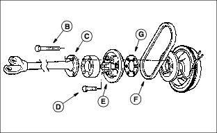
2. Remove three bolts (B) to disconnect drive shaft (C).
3. Remove three bolts (D) to remove outer sheave (E).
4. Remove belt (F) if it is to be replaced.
NOTE: To allow sheaves to fit closer together and increase belt tension, remove shim (G). Save shim for future use.
5. Remove shim (G) if belt is to be tightened. Leave shim in if installing a new belt.
6. Loosely install belt between sheave halves and start installing the three outer sheave-retaining bolts.
7. Rotate sheave assembly as bolts are tightened to allow belt to center in sheave halves and not be pinched in an OFF-CENTER position.