![]()
Introduction
Product Identification
Safety
Operating
Replacement Parts
Service Intervals
Service
Troubleshooting
Storage
Assembly
Install And Adjust Discharge Chute
Install and Adjust Discharge Chute Crank
Install and Adjust Auger Brake / Drive Cable
Adjust Auger Drive Belt Tension
Install And Adjust Speed Selector Linkage
Install and Adjust Traction Drive Cable
Specifications
Warranty
John Deere Quality Statement
Service Record
Copyright© Deere & Company

Assembly
Identify Snowblower Parts
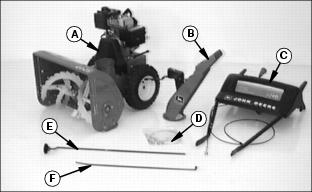
Bag Of Parts
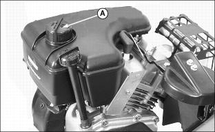
Add Engine Oil
NOTE: Remind customer to change oil after first two operating hours.
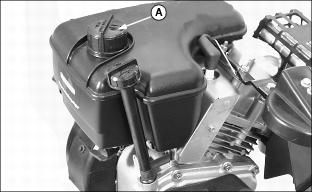
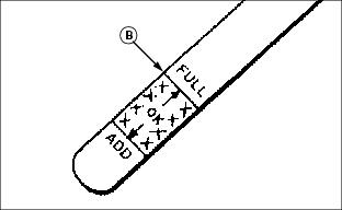
2. Add engine oil to bring level to the FULL mark (B) on dipstick.
· Add oil through dipstick tube (A).
Approximate crankcase capacity is 621 mL (21 fl. oz.)
3. Install and tighten dipstick.
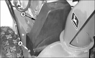
Connect Spark Plug Wire
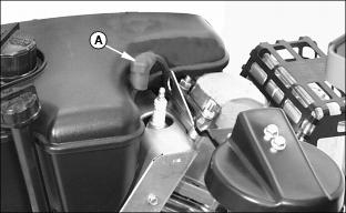
1. Install spark plug wire (A).
Add Fuel
1. Add a minimum amount of fuel to this unit. Some adjustments will require the engine running.
Approximate fuel tank capacity is 1.9 L (2 Qts.)
Extra Auger Drive Shear Bolts
Two extra auger drive shear bolts are included and attached to back of the handle bar assembly.
Remind customer to remove extra shear bolts and to store in a safe place.
Install Handle Bars
1. Locate handle bar assembly onto blower assembly:
2. Install four 5/16 x 5/8 in. flange head cap screws (A and B) on the left and right sides of unit.
Install And Adjust Discharge Chute
1. Apply a liberal amount of grease between auger housing and discharge chute.
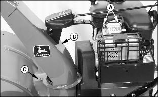
2. Install discharge chute (B) using two1/4 in. hex nuts and two 1/4 in. lock washers (A). Discharge chute must be under chute retainer (C). Do not tighten hardware:
3. Adjust discharge chute - straightness:
a. Adjust discharge chute and attaching bracket until chute is sitting square on auger housing.
b. Tighten attaching hardware (A).
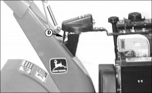
4. Adjust discharge chute - height:
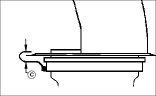
a. Loosen height adjusting hardware (D).
b. Adjust discharge chute until chute is located in the middle of the chute retainer (C).
Install and Adjust Discharge Chute Crank
Install Discharge Chute Crank
1. Install chute crank (A) through adjusting bracket (B), hole in console and gearbox (C).
2. Align cross drilled hole in chute crank with cross drilled hole in gear box.
3. Install large quick pull pin (D) to retain chute crank.
Adjust discharge chute crank - location:
1. Chute crank should be located in the center of the hole in the console, adjust as required.
2. Loosen adjusting bracket (B) hardware.
3. Move bracket up and down as needed.
5. If more adjustment is needed, loosen the four handlebar attaching bolts (E). Reposition handlebars a little to center hole around the chute crank. Tighten hardware.
Adjust discharge chute crank - tightness:
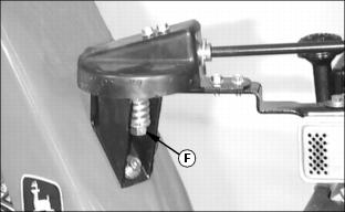
1. Operate chute crank. Crank should be tight enough so it will not move from engine vibration, but it should be loose enough to operate smoothly.
2. If chute crank is too loose, tighten nut (F).
3. If chute crank is too tight, loosen nut (F).
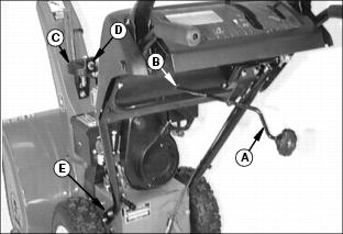
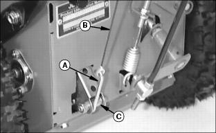
Install and Adjust Auger Brake / Drive Cable
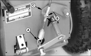
1. Connect auger brake / drive cable spring end (A) to tab on frame.
2. Position both nuts (B) midrange on the cable adjusting threads.
3. Connect cable to the brake / drive lever (C) and tighten both nuts.
Adjust Auger Brake / Drive Cable
1. Remove two cap screws (A) to remove belt cover (B).
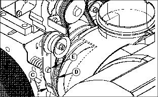
2. Check clearance between brake pad (C) and auger drive belt (D):
· With auger drive lever released, the brake pad (C) must contact auger drive belt (D).
NOTE: When the auger drive cable has some slack in it; that means maximum spring force is being applied to the brake arm (E).
3. Check auger drive cable (F), cable should have some slack in it. If cable is tight or very loose, change cable length by adjusting nuts (G).
Adjust Auger Drive Belt Tension
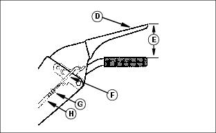
1. Start engine and run at full throttle.
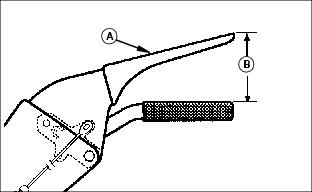
2. Slowly depress the auger drive lever (A) until the auger shaft begins to rotate. At this point the auger drive lever should be between 76 to 83 mm (3 to 3-1/4 in.) (B) from the handle grip.
3. If your dimension is not within this range, shut off the engine and adjust the auger drive belt tension as required.
NOTE: A 1.5 mm (1/16 in.) adjustment of the pulley will result in an approximate 6 mm (1/4 in.) change in the measurement (B).
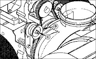
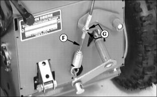
4. To adjust the belt tension, loosen the idler arm pulley lock nut (C) and move the pulley (D) to loosen or tighten the belt tension.
6. Repeat steps 1through 5 until adjusted properly.
Install And Adjust Speed Selector Linkage
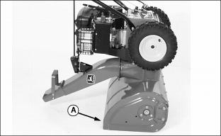
1. Tip machine forward onto housing (A).
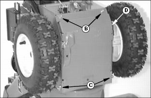
2. Remove two bolts (B) and loosen two bolts (C) to remove access panel (D).
3. Lower end of speed selector linkage:
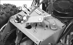
a. Assemble the speed selector linkage (E) with a 5/16 in. hex nut (F1) and a 5/16 in. lock nut (F2) onto the shift lever (G).
b. Do not tighten nuts (F1 and F2). Nuts will be tightened when adjusting the linkage.
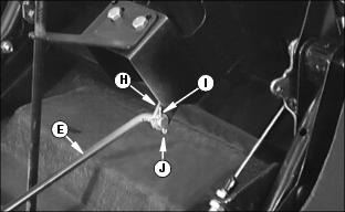
4. Upper end of speed selector linkage:
a. Put speed selector lever in the "6" position.
b. Assemble the speed selector linkage (E) onto the shifter lever (H) with one 3/8 in. flat washer (I) and one small quick pull pin (J).
IMPORTANT: Avoid damage! To properly adjust the speed selector linkage, the speed selector lever must be in the "R2" position. |
Adjust Speed Selector Linkage
1. Put speed selector lever in the "R2" position.
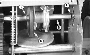
2. Slide hex shaft (M) to the right. Roll pin (L) will be up against the side frame. Hold hex shaft in the position.
3. Slide friction wheel (N) to the left until it is up against roll pin (K).
4. Tighten hex nut (F1) and locknut (F2) on the lower speed selector linkage.
5. Check to make sure friction wheel (N) is up against roll pin (K) and roll pin (L) is up against the side frame.
6. Check operation of shift lever linkage:
· Shift lever in "R2", the friction wheel should contact roll pin (K).
· Shift lever in "6", the friction wheel should not travel beyond the friction plate diameter.
7. Install access panel and return unit to its operating position.
8. Start engine and check for proper operation of the speed selector lever.
Install and Adjust Traction Drive Cable
1. Lower end of traction drive cable:
a. Connect link (A) to traction drive cable (B) eyelet.
b. Connect link (A) to the wheel drive clutch arm (C).
2. Upper end of traction drive cable:
a. Loosen lock nut (G) and remove threaded hooked end (F).
b. Connect the threaded hooked end (F) into the traction drive lever linkage.
c. Thread adjusting sleeve (H) onto the threaded hooked end (F).
d. Do not tighten lock nut (G).
Adjust Traction Drive Cable
1. Put speed selector lever in first gear.
2. Pull the wheel drive clutch arm (C) upward until you feel a positive stop. Hold the wheel drive clutch arm in this position.
3. Move the traction drive lever (D) until it is 83 - 95 mm (3-1/4 - 3-3/4 in.) (E) from the handle grip.
4. With the wheel drive clutch arm (C) held upward and the traction drive lever held down to dimension (E) there should be no slack in traction control cable, adjust the cable length as required:
· Lengthen or shorten traction control cable by turning adjusting sleeve (G).
5. Repeat steps 2- 4until there is no slack in cable.
Check Auger Gearbox Oil Level
1. Park unit on level surface.
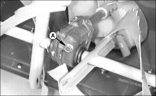
3. Fluid level should be at oil fill plug.
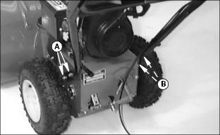
Check Tire Pressure
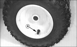
Tire pressure has been increased for shipping purposes. Check tire pressure (A) with an accurate gauge. Tire pressure should be: