![]()
Introduction
Product Identification
Safety
Operating
Replacement Parts
Service Intervals
Service
Engine Warranty Maintenance Statement
Cleaning And Gapping Spark Plug
Changing Auger Drive Belt Or Traction Drive Belt
Adjusting Impeller / Auger Brake
Adjusting Auger Drive Belt Tension
Adjusting Traction Drive Clutch
Adjusting Speed / Shift Linkage
Changing Headlight Light Bulb (Optional Equipment)
Troubleshooting
Storage
Assembly
Specifications
Warranty
John Deere Quality Statement
Service Record
Copyright© Deere & Company

Service
Engine Warranty Maintenance Statement
Maintenance, repair, or replacement of the emission control devices and systems on this engine, which are being done at the customers expense, may be performed by any nonroad engine repair establishment or individual. Warranty repairs must be performed by an authorized John Deere dealer.
Avoid Fumes
Grease
The following greases are preferred:
· John Deere Multi-Purpose SD Polyurea Grease
· John Deere Multi-Purpose HD Lithium Complex Grease
· John Deere Moly High Temperature EP Grease
If not using any of the preferred greases, be sure to use a general all-purpose grease with an NLGI grade No.2 rating.
Wet or high speed conditions may require use of a special-use grease. Contact your Servicing dealer for information.
Engine Oil
Use oil viscosity based on the expected air temperature range during the period between oil changes.
The following John Deere oils are preferred:
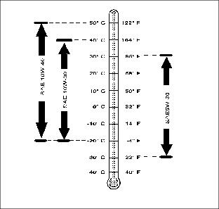
Other oils may be used if above John Deere oils are not available, provided they meet the following specification:
· API Service Classification SG or higher
Gear Oil
Use oil viscosity based on the expected air temperature range during the period between oil changes.
The following John Deere gear case oil is PREFERRED:
The following John Deere gear case oil is also recommended if above preferred oil is not available:
Other gear case oils may be used if above recommended John Deere gear case oils are not available, provided they meet the following specification:
· API Service Classification GL-5.
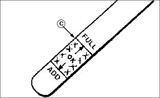
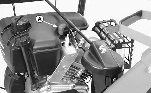
Checking Engine Oil Level
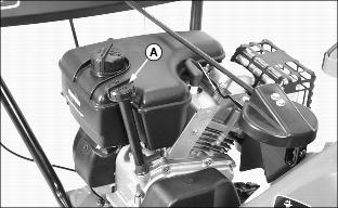
1. Park snowblower on a level surface.
2. Clean area around dipstick.
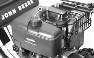
3. Remove dipstick (A). Wipe it off with clean, lint free towel.
4. Install and tighten dipstick. Remove dipstick and locate oil level.
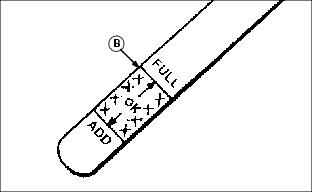
5. Add oil to bring level to the FULL mark on dipstick.
· Add oil through dipstick tube.
6. Install and tighten dipstick.
Changing Engine Oil
NOTE: Change oil after first two operating hours.
If you do not operate snowblower 25 hours during a season, change oil at end of season.
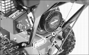
1. Run engine a few minutes to warm oil. Oil will flow more freely and carry away more contamination when warm.
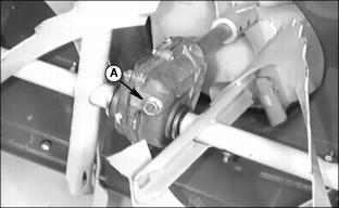
2. Clean area around oil drain plug (A).
3. Position unit so engine oil drain plug is lowest point on engine.
4. Remove oil drain plug (A) and dipstick (B) to drain engine oil.
5. Install oil drain plug and tighten.
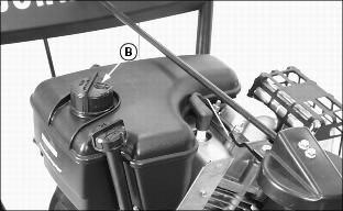
6. Add oil to bring level to the FULL mark on dipstick.
· Add oil through dipstick tube.
Approximate crankcase capacity:
· Install and tighten dipstick.
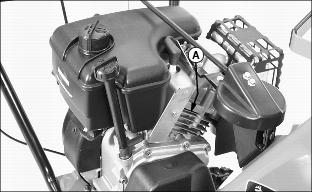
Cleaning And Gapping Spark Plug
Clean and gap spark plug at the beginning of season or every 25 operating hours.
1. Clean area around spark plug.
2. Disconnect spark plug wire (A).
3. Remove and inspect spark plug:
· Clean plug and check for damage, replace if necessary.
· If plug is in good condition, check gap.
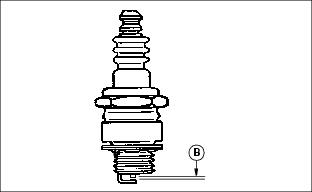
4. Check and adjust spark plug gap (B):
5. Install spark plug and tighten to 20 N·m (15 lb-ft.).
Cleaning Cylinder Fins
· Every 100 operating hours or yearly (more often if conditions require) remove cooling shrouds and clean cooling fins.
· Also clean external surfaces of your engine of dust, dirt, and oil deposits which can contribute to improper cooling.
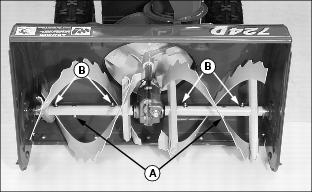
Replacing Shear Bolts
NOTE: Two extra shear bolts were included with your snowblower.
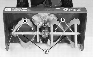
2. Inspect both shear bolts (A). If necessary, remove broken shear bolt(s).
3. Lubricate auger shaft at four points (B). Turn auger shaft several times to distribute grease.
4. Line up holes in auger with hole in auger shaft.
5. Install new shear bolt and lock nut.
Checking Tire Pressure
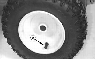
Check tires for wear or damage, replace as required.
Check tire pressure (A) with an accurate gauge. Tire pressure should be:
Adjusting Carburetor
NOTE: The carburetor is calibrated by the engine manufacturer and should not require any adjustments.
If engine is operated at altitudes above 1829 m (6,000 ft.), some carburetors may require a special high altitude main jet. See your John Deere dealer.
Possible engine surging will occur at high rpm when the transmission is in neutral ("N") and the PTO switch is in the OFF position. This is a normal condition due to the emission control system.
If engine is hard to start or runs rough, check the Troubleshooting section of this manual.
After performing the checks in the troubleshooting section and your engine is still not performing correctly, contact your John Deere dealer.
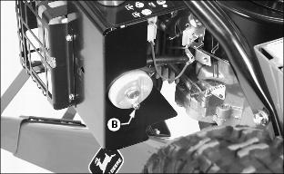
Drain Carburetor
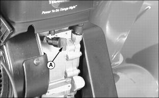
To remove fuel from the carburetor bowl:
· Turn fuel shut off valve (A) to the closed (OFF) position.
· Place a small container under the carburetor.
· Press drain plug (B) in until all fuel is removed from bowl.
Lubricating Auger Gearbox
Check oil level at the beginning of season or every 25 operating hours.
1. Clean area around fill plug.
2. Park unit on level surface.
4. Fluid level should be at oil fill plug.
Lubricating Auger Shaft
Auger shaft should be lubricated at the beginning of season or every 25 operating hours.
2. Turn auger on shaft while applying grease to grease fittings (B).
Lubricating Internal Drive
Internal drive should be lubricated at the beginning of season or every 25 operating hours.
1. Park snowblower on a hard, smooth surface.
2. Stop engine, remove key, wait for all moving parts to stop.
3. Remove wire from spark plug to prevent accidental starting.
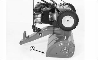
4. Tip machine forward onto housing (A).

5. Remove two bolts (B) and loosen two bolts (C) to remove access panel (D).
IMPORTANT: Avoid damage! DO NOT allow grease or oil to get on friction wheel and drive disc (E) or drive belts. |
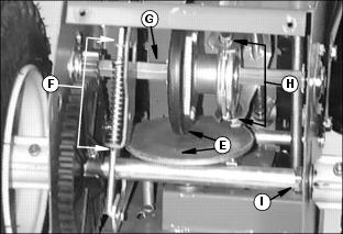
· Wheel drive spring assembly (F).
Lubricating Discharge Chute
Discharge chute should be lubricated at the beginning of season or every 25 operating hours.
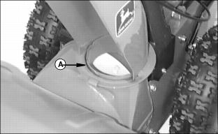
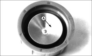
· Turn discharge chute while applying grease to base (A).
Changing Friction Wheel
1. Park snowblower on a hard, smooth surface.
2. Stop engine, remove key, wait for all moving parts to stop.
3. Remove wire from spark plug to prevent accidental starting.
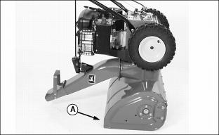
4. Tip machine forward onto housing (A).

5. Remove two bolts (B) and loosen two bolts (C) to remove access panel (D).
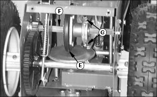
IMPORTANT: Avoid damage! To ensure proper machine operation, DO NOT allow grease or oil to get on friction wheel (E), drive disc or drive belts. |
6. Remove right hand wheel and tire.
7. Remove bearing flange on right side of frame
8. Slide friction wheel assembly (E) and hex shaft (F) to the right until left end of hex shaft comes free of the left bearing and pinion.
9. Remove three cap screws securing friction wheel to hub and remove friction wheel.
10. Secure new friction wheel onto hub with three cap screws. Tighten cap screws to 11-13 N·m (8-10 lb-ft).
11. Position friction wheel hub in forks (G). Be sure washers are in place on bearing flange pins. Slide hex shaft to left and into pinion and left bearing with flat washers in position. Pinion gear must mesh with large gear.
12. Install bearing flange and right hand tire and wheel.
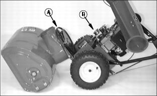
Changing Auger Drive Belt Or Traction Drive Belt
1. Park snowblower on a hard, smooth surface.
2. Stop engine, remove key, wait for all moving parts to stop.
3. Remove wire from spark plug to prevent accidental starting.
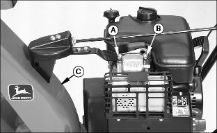
4. Disconnect auger chute rotation linkage:
· Remove 1/4 x 1-1/4 cap screw (A), Lock washer, Flat washer and spacer.
· Remove 5/16 x 5/8 cap screw (B), Lock washer and Flat washer.
· Lift discharge chute (C) off housing.
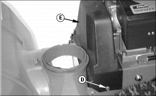
5. Remove two cap screws (D) to remove belt cover (E).
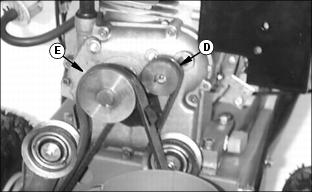
6. Disconnect belts from engine:
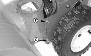
7. Loosen lower cap screws (G).
8. Support handle bars and remove upper cap screws (F).
9. Push down on handle bars. Unit will separate, put handle bars on floor.
10. Inspect drive belts. Remove and replace belts as required.
Assemble Unit
1. Install upper and lower hardware (F and G).
2. Install drive belts on engine.
4. Install discharge chute and connect auger linkage.
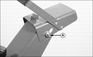
Adjusting Chute Crank

1. Park snowblower on a hard, smooth surface.
2. Stop engine, remove key, wait for all moving parts to stop.
3. Remove wire from spark plug to prevent accidental starting.
· If chute crank is too tight, loosen nut (A).
· If chute crank is too loose, tighten nut (A).
Adjusting Chute Deflector
1. Park snowblower on a hard, smooth surface.
2. Stop engine, remove key, wait for all moving parts to stop.
3. Remove wire from spark plug to prevent accidental starting.
· If chute deflector is too loose, tighten nut (A).
· If chute deflector is too tight, loosen nut (A).
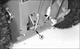
Adjusting Impeller / Auger Brake
1. Park snowblower on a hard, smooth surface.
2. Stop engine, remove key, wait for all moving parts to stop.
3. Remove wire from spark plug to prevent accidental starting.
4. Remove two cap screws (A) to remove belt cover (B).
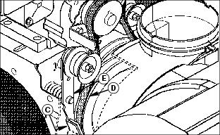
5. Check clearance between brake pad (C) and auger drive belt (D):
· With auger drive lever released, the brake pad (C) must contact auger drive belt (D).
NOTE: When the auger drive cable has some slack in it; that means maximum spring force is being applied to the brake arm (E).
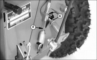
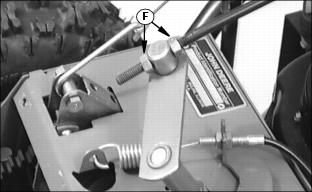
6. Check auger drive cable (F), cable should have some slack in it. If cable is tight or very loose, change cable length by adjusting nuts (G).
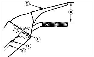
Adjusting Auger Drive Belt Tension
1. Park snowblower on a hard, smooth surface.
2. Stop engine, remove key, wait for all moving parts to stop.
3. Remove two cap screws (A) to remove belt cover (B).
4. Check impeller / auger brake adjustment before adjusting tension on the auger drive belt.
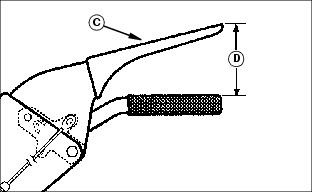
5. Start the engine and run at full throttle.
6. Slowly depress the auger drive lever (C) until the auger shaft begins to rotate. At this point the auger drive lever should be between 76 to 83 mm (3 to 3-1/4 in.) (D) from the handle grip.
7. If your dimension is not within this range, shut off the engine and adjust the auger drive belt tension as required.
NOTE: A 1.5 mm (1/16 in.) adjustment of the pulley will result in an approximate 6 mm (1/4 in.) change in the measurement (D).

8. To adjust the belt tension, loosen the idler arm pulley lock nut (E) and move the pulley (F) to loosen or tighten the belt tension.
10. Repeat steps 5 through 8 until adjusted properly.
Adjusting Traction Drive Clutch
Adjust traction clutch to compensate for wear of friction wheel when slippage occurs.
1. Park snowblower on a hard, smooth surface.
2. Stop engine, remove key, wait for all moving parts to stop.
3. Remove wire from spark plug to prevent accidental starting.
4. Put speed selector lever (A) in first gear.
5. Pull the wheel drive clutch arm (B) upward until you feel a positive stop. Hold the wheel drive clutch arm in this position.
6. Move the traction drive lever (C) until it is 83 - 95 mm (31/4 - 3-3/4 in.) (D) from the handle grip.
7. With the wheel drive clutch arm (B) held upward and the traction drive lever held down to dimension (D) there should be no slack in cable (E), adjust the cable length as required:
b. Lengthen or shorten cable (E) by turning adjusting sleeve (G).
d. Repeat steps 5 - 7 until there is no slack in cable.
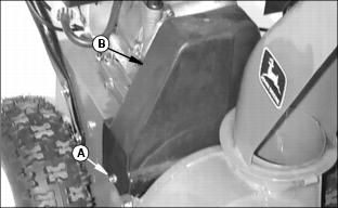
Adjusting Speed / Shift Linkage
1. Park snowblower on a hard, smooth surface.
2. Stop engine, remove key, wait for all moving parts to stop.
3. Remove wire from spark plug to prevent accidental starting.
4. Put speed selector lever (A) in reverse R2 position.

5. Tip machine forward onto housing (B).
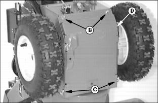
6. Remove two bolts (C) and loosen two bolts (D) to remove access panel (E).
7. Loosen both lock nuts (F) on the shift lever linkage.
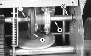
8. Slide hex shaft (H) to the right. Roll pin (G) will be up against the side frame. Hold shaft in the position.
9. Slide friction wheel (I) to the left until it is up against roll pin (J).
10. Tighten both lock nuts (F) on shift lever swivel.
11. Check to make sure friction wheel (I) is up against roll pin (J) and roll pin (G) is up against the side frame.
12. Check operation of shift lever linkage:
· Shift lever in "R2", the friction wheel should contact roll pin (J).
· Shift lever in "6", the friction wheel should not travel beyond the friction plate diameter.
13. Install access panel and return unit to its operating position.
14. Start engine and check for proper operation of the speed selector lever.
Filling Fuel Tank
Use regular grade 87 octane unleaded fuel.
Add John Deere fuel stabilizer to fuel before using it in your machine to prevent engine damage due to stale fuel. Follow directions on stabilizer container.
1. Stop engine, let it cool several minutes before you add fuel.
2. Remove dirt and debris from tank area.
4. Fill tank with fuel only to bottom of filler neck.
Cleaning Fuel Cap Vents
· Clean in nonflammable solvent.
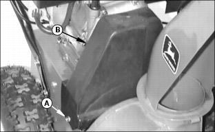
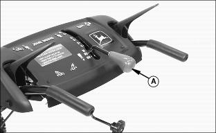
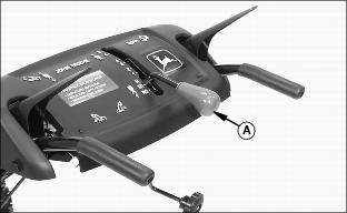
Changing Headlight Light Bulb (Optional Equipment)
1. Stop engine, remove key, wait for all moving parts to stop.
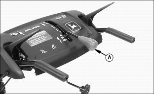
2. Move controls to get more hand room under console:
3. Move shift lever (A) to the "R2" position.
NOTE: It is not necessary to disconnect the green wire (C) or the black wire (D) to remove the light bulb holder.
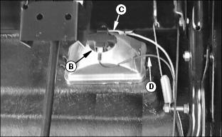
4. Turn light bulb holder (B) counterclockwise 1/4 of a turn and remove it from the headlight.
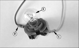
5. Turn light bulb (E) counter -clockwise 1/4 of a turn and remove it from the holder.
6. Remove and replace defective light bulb (E).
7. Install light bulb holder (B). Turn clockwise 1/4 of turn to tighten.