Introduction
Safety Signs
Controls
Operating
Replacement Parts
Service Machine Safely
Service Interval Chart
Service Engine
Service Engine
Service Transmission
Service Steering & Brakes
Adjusting Drive Wheel Belt Tension
Service Mower
Service Electrical
Service Miscellaneous
Troubleshooting
Storing Machine
Assembly
Specifications
Warranty
Service Literature
CopyrightŠ Deere & Company

Service Steering & Brakes
Grease
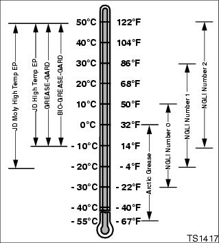
Use grease based on the expected air temperature range during the service interval.
The following greases are preferred:
ˇ John Deere Moly High Temperature EP Grease.
ˇ John Deere High Temperature EP Grease.
Other greases may be used are:
ˇ SAE Multipurpose EP Grease with 3 to 5 percent molybdenum disulfide.
ˇ Greases meeting Military Specification MIL-G-10924C may be used as arctic grease.
Adjusting Brakes
IMPORTANT: Avoid damage! Due to initial brake wear and brake material being seated, the brakes should be checked and adjusted after the first 25 hours of use. |
NOTE: This adjustment should be performed on a hard rough surface such as a blacktop parking lot.
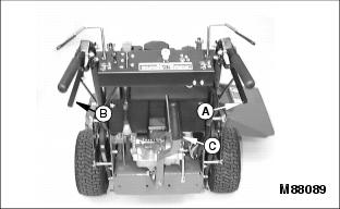
Adjust right hand (A) and left hand (B) brakes as required. Brakes should be adjusted equally.
Test brakes:
ˇ Lock the brake levers. (See Setting Parking Brake in the Operating section).
ˇ Put transmission lever (C) in neutral "N".
ˇ Push and pull machine. Rear wheels (drive wheels) should skid.
ˇ Properly adjusted brakes MUST prevent machine from moving.
Adjust brakes:
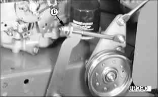
ˇ To increase brake tension, tighten lock nut (D).
ˇ To decrease brake tension, loosen lock nut (D).
Replacing Drive Wheel Belt
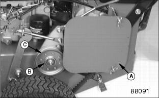
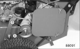
2. Remove nut (B) and idler (C).
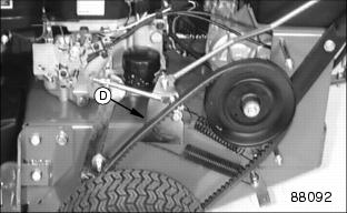
3. Remove old drive belt (D) and install new drive belt.
4. Install idler (C) as required to tighten new drive belt and tighten nut (B).
5. Check drive belt tension and adjust if necessary. (See Adjusting Drive Belt Tension in this section.)
Adjusting Drive Wheel Belt Tension
IMPORTANT: Avoid damage! Due to belt stretching, the tension on the drive wheel belts should be checked and adjusted after the first 25 hours of use. |
For best overall performance always adjust both left and right drive wheel belts equally.
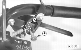
1. Install something that is approximately 8 mm (5/16 in) in diameter (A)-such as a 8 mm bolt (B) in-between the brake lever stud and the brake lever lock.
3. Move sheave (D) to tighten drive belt.
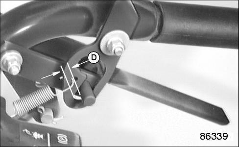
NOTE: If gap (D) is less than 6mm (1/4 in.) the vehicle's traction may be restricted.
If gap (D) is greater than 12 mm (1/2 in.) the belt may not declutch, when the brakes are applied.
6. A properly adjusted drive belt will show a gap (D) approximately 8 mm (5/16 in) between the brake lever stud and the brake lever lock.

