Introduction
Safety Signs
Controls
Operating
Replacement Parts
Service Machine Safely
Service Interval Chart
Service Engine
Service Engine
Service Transmission
Service Steering & Brakes
Service Mower
Service Electrical
Service Miscellaneous
Troubleshooting
Storing Machine
Assembly
Assemble GS75 - Set-Up And Activate Battery
Identify Parts (48/54-Inch Decks)
Bag of Parts: (48/54-Inch Decks)
Assemble 48/54-Inch Mower Deck
Identify Parts (36-Inch Decks)
Attach Mower Deck (36-Inch Decks)
Install Drive Belt (PTO Clutch To Mower Deck)
Check Mower Deck Timing (36-Inch Decks)
Installing Engine Service Labels
Specifications
Warranty
Service Literature
CopyrightŠ Deere & Company

Assembly
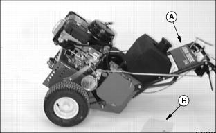
Assembly Instructions
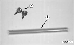
Bag of Parts (GS30 And GS45)
B - Oil Drain Hose (GS30 Only)
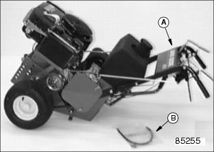
Identify Parts (GS75)
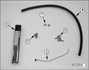
Bag of Parts (GS75)
Assemble GS75 - Set-Up And Activate Battery
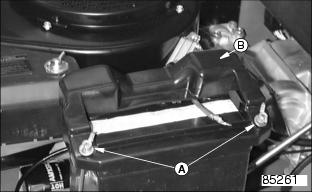
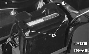
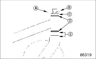
1. Loosen both wing nuts (A) to remove the battery cover (B).
2. Remove battery from the tray.
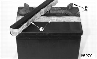
3. Remove and discard safety tape (C) from across battery cells and battery cap.
4. Remove protective plastic cover (D) from the positive (+) battery post.
5. Remove and discard battery cell plugs.
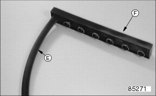
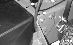
6. Install battery vent hose (E) on battery cap (F).
IMPORTANT: Avoid damage! To prevent damage to machine from spilled electrolyte, remove the battery from the machine. |
ˇ Only use battery acid with a 1.265 specific gravity.
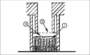
ˇ Slowly add acid (H) to each cell. The solution should be 6 mm (1/4 in.) above plates (I), but NO HIGHER THAN 6 mm (1/4 in.) from the bottom of the filler neck (G).
8. Install the battery cap before charging the battery.
9. Charge the battery for a MINIMUM of 30 minutes at 5-10 amps. If your battery charger has a Deep Cycle or Maintenance Free setting, use this setting to charge the battery. Failure to charge the battery before use will reduce battery performance and life.
10. Install the battery on battery tray. Position battery so that terminals are towards the engine and drain vent is toward the front.
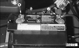
ˇ Connect red positive (+) cable (J) to battery using one M6 screw and M6 hex nut. Make sure connection is tight.
ˇ Connect black negative (-) cable (K) to battery using one M6 screw and M6 hex nut. Make sure connection is tight.
ˇ Apply Anti-Corrosion Grease (DuBois MPG-2 Polymer Grease) to terminals to prevent corrosion.
12. Install battery cover (B) and tighten wing nuts (A) just tight enough to hold down battery.
NOTE: When a 36-Inch Mower Deck ia attached to a GS75 do not attach vent hose to frame with tie strap. Vent hose will be routed between frame and belt cover.
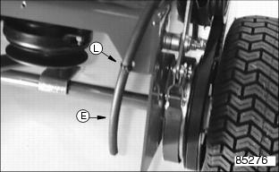
ˇ Route battery vent hose (E) down under power deck.
ˇ Fasten vent hose to frame with plastic tie strap (L).
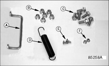
Identify Parts (48/54-Inch Decks)
Bag of Parts: (48/54-Inch Decks)
C - M12 x 30 Cap Screws(6 Used)
E - M8 x 20 Carriage Bolts (2 Used)
Assemble 48/54-Inch Mower Deck
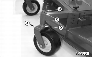
Install Caster Wheels
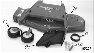
1. Install both caster wheels (A) into mower deck frame:
ˇ Position 2 or 3 washers (D).
ˇ Position 2 or 3 washers (C) and snap ring (B) on top of spindle.
2. Lubricate spindle grease fitting (E) with John Deere Moly High Temperature EP Grease or an equivalent.
Install Discharge Chute
1. Position discharge chute assembly (A) on mower deck.
NOTE: M8 Carriage bolts should be installed with the bolt head to the inside of the chute opening to avoid grass clippings from collecting on the hardware.
3. Install and tighten two M8 x 20 carriage bolts and M8 locknuts (C).
Attach Mower Deck (48/54-Inch Decks)
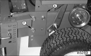
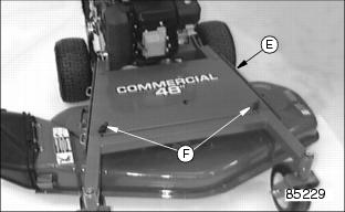
1. Remove both knobs (A) and belt cover (B).
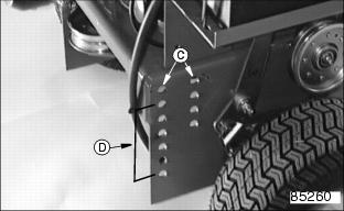
NOTE: Align mower deck mounting brackets (E) with the top set of mounting holes (C). Disregard all the different mounting holes (D) in the power deck frame. They are not used in this application.
2. Attach mower deck mounting brackets (E) to the top set of mounting holes (C) in the power deck using:
ˇ Six M12 x 30 cap screws (F).
ˇ Tighten lock nuts to 140 Nˇm (105 lb-ft).
Install Drive Belt (PTO Clutch To Mower Deck)
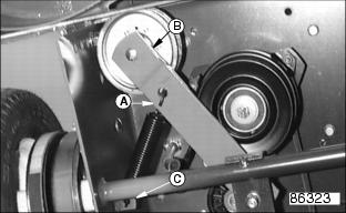
1. Remove and discard plastic tie strap from idler arm.
ˇ Attach long hooked end of spring (A) on idler arm (B).
ˇ Attach short hooked end of spring on frame tab (C).
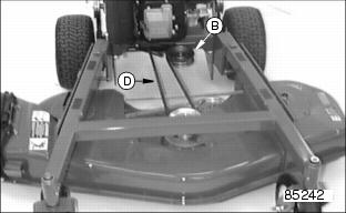
ˇ Install drive belt (D) over PTO clutch drive sheave.
ˇ Install drive belt over mower deck drive sheave and at the same time pull spring loaded idler arm (B) to loosen belt tension.
ˇ Make sure drive belt is properly routed around the spring loaded idler (B) for proper belt tension.
4. Install belt cover (E) and both knobs (F).
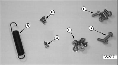
Identify Parts (36-Inch Decks)
Bag of Parts (36-Inch Decks)
B - M8 x 20 Carriage Bolts (2 Used)
C - M6 Self-Tapping Screws (2 Used)
E - M12 x 30 Cap Screws (4 Used)
F - M12 x 35 Cap Screws (2 Used)
Attach Mower Deck (36-Inch Decks)
When you attach the mower deck to the power unit frame you will also be setting the mower deck cutting height. The mower deck cutting heights range from 19-114 mm (3/4-4 1/2 in).
The mower deck height adjustment consists of:
ˇ Four sets of mounting holes in the power unit frame.
ˇ Two sets of mounting holes in the caster wheel supports.
Attach Mower Deck And Set Cutting Height
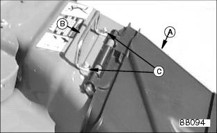
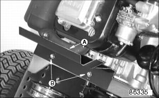
1. Attach heat shield (A) to power unit frame using two M6 self-tapping screws (B).
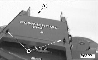
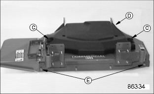
2. Remove both knobs (C) and plastic belt cover (D).
3. Remove both shipping brackets and hardware from mower deck. Discard brackets and hardware (save M8 locknuts). Install two M8 x 20 carriage bolts with the bolt head to the inside of the mower deck and M8 locknuts (E).
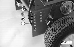
4. Choose a mower deck cutting height and start attaching the mower deck to the power unit frame as listed below.
If necessary, see label on mower deck.
ˇ Use holes (F) for a cutting height of 102-114 mm (4-4 1/2 in).
ˇ Use holes (G) for a cutting height of 76-89 mm
(3-3 1/2 in).
ˇ Use holes (H) for a cutting height of 51-64 mm
(2-2 1/2 in).
ˇ Use holes (I) for a cutting height of 19-38 mm
(3/4-1 1/2 in).
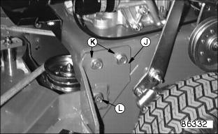
5. Connect mower deck (J) to mounting holes (F,G,H or I) in the power unit frame using:
ˇ Four M12 x 30 cap screws (K).
ˇ Two M12 x 35 cap screws (L).
ˇ Tighten lock nuts to 140 Nˇm (105 lb-ft).
NOTE: The caster wheel supports are attached to the mower deck at the factory. They should be attached to the bottom set of mounting holes. If necessary, remove them and install in the top mounting holes.
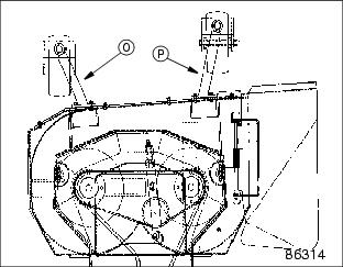
6. Connect both caster wheel supports (O and P) to mounting holes in the mower deck frame using eight M8 carriage bolts and M8 locknuts. Tighten locknuts to
25 Nˇm (18.5 lb-ft).
Always adjust left and right caster wheel supports equally:
NOTE: When the bottom mounting holes are used. Install the lower carriage bolts with the bolt head to the inside of the mower deck to avoid grass clippings from collecting on the hardware.
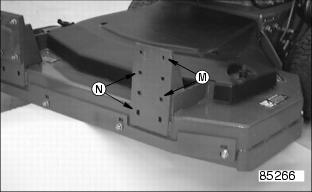
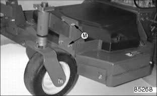
ˇ Use top mounting holes (M) for cutting heights of 19-64 mm (3/4-2 1/2 in).
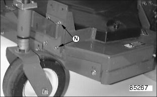
ˇ Use bottom mounting holes (N) for cutting heights of 64-114 mm (2 1/2-4 1/2 in).
If necessary, see label on mower deck.
NOTE: Identify left (O) and right (P) caster wheel supports prior to attaching them to the mower deck frame.
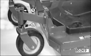
7. Assemble and install caster wheels into caster wheel brackets. Install spacers according to desired mower deck cutting height:
Use spacers to raise and lower caster wheels as required. Always adjust left and right caster wheels equally.
NOTE: The caster wheel brackets must be attached to the mower deck in the upper set of mounting holes (M).
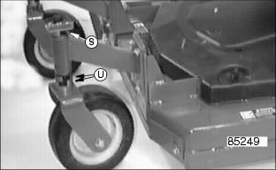
ˇ Decks set at 19 mm (3/4 in), use no (0) spacers at location (U).
ˇ Decks set at 25 mm (1 in), use one (1) spacer at location (U).
ˇ Decks set at 38 mm (1 1/2 in), use two (2) spacers at location (U).
ˇ Decks set at 51mm (2 in), use three (3) spacers at location (U).
ˇ Decks set at 64 mm (2 1/2 in), use four (4) spacers at location (U).
Always store extra spacers on caster spindle at location (S).
Use spacers to raise and lower caster wheels as required. Always adjust left and right caster wheels equally.
NOTE: The caster wheel brackets must be attached to the mower deck in the lower set of mounting holes (N).
ˇ Decks set at 64 mm (2 1/2 in), use no (0) spacers at location (U).
ˇ Decks set at 76 mm (3 in), use one (1) spacer at location (U).
ˇ Decks set at 89 mm (3 1/2 in), use two (2) spacers at location (U).
ˇ Decks set at 102 mm (4 in), use three (3) spacers at location (U).
ˇ Decks set at 114 mm (4 1/2 in), use four (4) spacers at location (U).
Always store extra spacers on caster spindle at location (S).
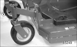
8. Lubricate spindle grease fittings (V) with John Deere Moly High Temperature EP Grease or an equivalent.
Install Drive Belt (PTO Clutch To Mower Deck)
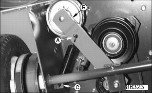
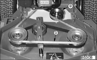
1. Remove and discard plastic tie strap from idler arm.
ˇ Attach long hooked end of spring (A) on idler arm (B).
ˇ Attach short hooked end of spring on frame tab (C).
ˇ Install drive belt (D) over PTO clutch drive sheave.
ˇ Install drive belt over mower deck drive sheaves and at the same time pull spring loaded idler arm (B) to loosen belt tension.
ˇ Make sure drive belt is properly routed around the spring loaded idler (B) for proper belt tension.
Check Mower Deck Timing (36-Inch Decks)
NOTE: Due to mower blade over-lap, the mower blades will eventually collide if the Timing is not checked and adjusted on a regular basis.
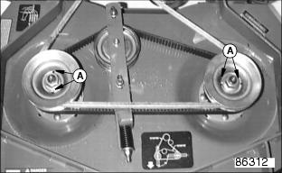
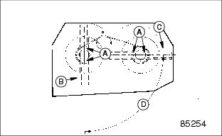
1. Note the position of the drain holes (A) in the spindle sheaves. These drain holes are in alignment with the mower blades.
2. A properly timed mower deck must have the mower blades (B) and (C) at 90° (D) from each other.
3. For a quick check on mower deck timing, sheave drain holes (A) should be approximately 90° from each other.
4. If necessary, adjust the mower deck timing. (See Adjusting Mower Deck Timing And Adjusting Timing Belt Tension in the Service - Mower section)
5. Install belt shield (E). When a 36-Inch Mower is attached to a power unit equipped with electric start, route the battery vent hose (F) between frame and belt cover.
Check Tire Pressure
1. Check tire pressure with an accurate gauge.
2. Adjust air pressure as required:
Remove Shipping Bracket
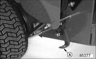
Removal of both shipping brackets (A) is not required. Customer may want to use the shipping brackets as a tie down point.
Check Machine Safety System
Perform safety system check to make sure the electronic safety interlock circuit is functioning properly. Perform all six tests.
(see Testing Safety System in the Operating section.)
Check Mower Deck Level
After unit is completely assembled check the mower deck level.
Check the "Front to Rear" and "Side to Side" level. See the Service - Mower section for leveling procedures on 36, 48 and 54 inch mower decks.
Break-In Electric PTO Clutch
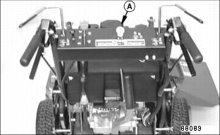
1. Start engine and push throttle lever up to full throttle ) position.
2. With no load on mower, ENGAGE PTO switch knob (A) and allow mower to run for 10 seconds.
ˇ DISENGAGE PTO switch knob and wait 10 seconds.
3. Repeat Step 2 for 12-15 cycles.
PTO clutch is now properly burnished.
Installing Engine Service Labels
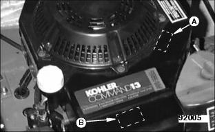
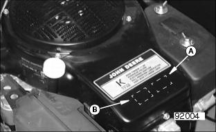
NOTE: Spanish language labels indicating engine service requirements are provided in the bag of parts. Please install if necessary.
For Model GS30 (Kohler)
1. Install Air Cleaner Maintenance label on engine shroud (B) at front top of engine.
2. Install Oil Servicing label on engine shroud (A) to the side of the existing label.
For Model GS45 and GS75 (K Series)
1. Install the Air Cleaner Maintenance label on the engine shroud (A) below the engine label.
2. Install the Oil Servicing label on the engine shroud (B) below the engine label.

