![]()
Introduction
Safety Signs
Controls
Operating
Replacement Parts
Service Safely
Service
Engine Warranty Maintenance Statement
Cleaning and Gapping Spark Plug
Replacing the Belt and Adjusting the Cable Spring
Troubleshooting
Storing Machine
Assembly
Specifications
Warranty
John Deere Service Literature
John Deere Quality Statement
Copyright© Deere & Company

Service
Service Intervals
Service Record
Engine Warranty Maintenance Statement
Maintenance, repair, or replacement of the emission control devices and systems on this engine, which are being done at the customers expense, may be performed by any nonroad engine repair establishment or individual. Warranty repairs must be performed by an authorized John Deere dealer.
Engine Oil
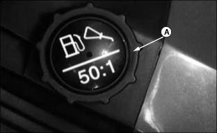
Mix oil and gasoline according to instructions.
The following oil is preferred:
· John Deere TWO-CYCLE ENGINE OIL
Other oils may be used if above preferred John Deere oil is not available, provided they meet one of the following specifications:
· SAE Standard J2116 or Classifications TA, TB, TC, or TD
· API Classification TC or higher
· NMMA Classifications TC-W or TC-WII or higher
JASO Classifications FA, FB, or FC or higher
Fuel
Unleaded fuel is recommended. Regular leaded gasoline with an anti-knock index of 87 or higher may also be used, but the unleaded fuel will burn cleaner and leave less unburned deposits in the combustion chamber. DO NOT use fuel that has been stored for a long time.
Mixing Fuel
DO NOT mix fuel in machine fuel tank.
1. Fill container with half of the gasoline.
2. Add all the oil. Fasten lid.
4. Pour in remaining gasoline.
Filling Fuel Tank
2. DO NOT fill tank to top; fuel can expand.
Grease
Use grease based on the expected air temperature range during the service interval.
The following greases are preferred:
· John Deere Moly High Temperature EP Grease.
· John Deere High Temperature EP Grease.
Other greases may be used are:
· SAE Multipurpose EP Grease with 3 to 5 percent molybdenum disulfide.
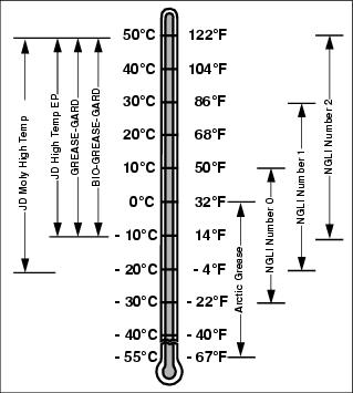
· Greases meeting Military Specification MIL-G-10924C may be used as arctic grease.
Lubricating the Auger Bail
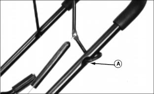
1. Apply oil to the pivot point (A) on each side.
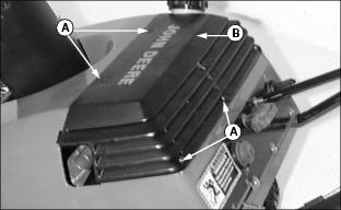
Lubricating the Idler Arm
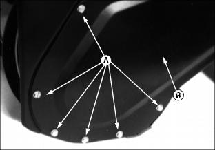
1. Remove the six screws (A) and belt cover (B).
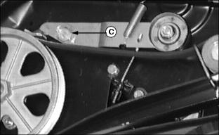
2. Apply a drop of oil to the idler arm at point (C).
3. Pivot the auger bail up and down several times.
Cleaning and Gapping Spark Plug
2. Remove the five screws (A) and shroud (B). Install the cap.
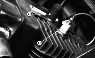
3. Disconnect the plug wire (C).
5. Carefully scrape or wire brush the carbon from the plug.
6. Inspect the plug for damage: cracks, pits, etc. Replace a damaged plug.
7. Adjust the gap: 0.8 mm (0.030 in.).
8. Install and tighten the plug.
10. Install the fuel tank cap.
Adjusting Carburetor
NOTE: The carburetor is calibrated by the engine manufacturer and should not require any adjustments.
NOTE: If engine is operated at altitudes above 1829 m (6,000 ft.), some carburetors may require a special high altitude main jet. See your John Deere dealer.
NOTE: Possible engine surging will occur at high rpm when the machine is in neutral ("N") and the auger is disengaged. This is a normal condition due to the emission control system.
If engine is hard to start or runs rough, check the TROUBLESHOOTING section of this manual.
After performing the checks in the troubleshooting section and your engine is still not performing correctly, contact your John Deere dealer.
Adjusting the Belt Tension
1. Disconnect spark plug wire.
2. Remove the six screws and the belt cover. See Lubricating the Idler Arm in this section.
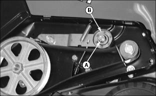
4. Move the sheave (B) to the bottom of the idler arm slot. If the sheave is already in the bottom position, replace the belt.
See Replacing the Belt in this section.
Replacing the Belt and Adjusting the Cable Spring
1. Disconnect spark plug wire.
2. Remove the six screws and the belt cover. See Lubricating the Idler Arm in this section.
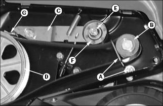
3. Remove nut and belt guide (A). Move the belt guide away from the belt. Roll the belt off the engine drive pulley (B).
4. Hold the idler arm (C) down to move the brake off the belt. Remove the belt from the auger drive pulley (D).
5. Loosen the nut (E). Move the sheave (F) to the top of the idler arm slot. Tighten the nut.
IMPORTANT: Avoid damage! The auger should stop turning when you release the bail. When the bail is engaged, there MUST be clearance between the brake arm and the belt. |
7. Install belt guide and tighten nut (A).
8. If the auger does not stop turning when you release the bail, check the cable spring adjustment: The cable should be slightly slack (no tension) when the auger bail is in the forward (released) position and the brake arm (G) should contact the belt.
NOTE: The black boot is shown removed from the spring in the picture with step 10.
9. To adjust the cable spring, remove the black boot from the spring:
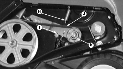
· Remove the end of the spring (H) from the hole (I) in the idler arm.
· Remove the belt (J) from the bottom of the idler pulley (K). Put the belt on top of the idler pulley as shown.
· Remove the end of the cable spring from the auger bail.
· Remove the black boot from the spring.
· Attach the end of the spring to the auger bail.
10. To adjust the cable spring:
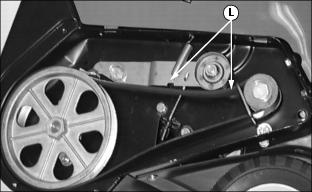
· Install the belt and idler spring in operating position (L).
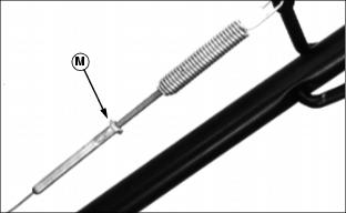
· Turn the cable fitting below the nut until the cable is slightly slack.
11. Remove the idler spring and belt and install the boot.
12. Install the belt, idler spring, and belt cover.
Replacing the Scraper Blade
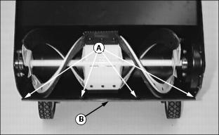
1. Remove the nuts (A), bolts and blade (B).
2. Install the new blade, bolts and nuts.
Freeing the Auger Cable
1. Thaw the block (A) and conduit (B) so the cable moves freely.
2. Work grease into the opening on the top of the block where the cable enters. See Grease in this section.