![]()
42-Inch for LX & GT Series Lawn & Garden Tractors
Introduction
Safety Signs
Preparing Vehicle
Installing
Removing and Storing
Operating
Replacement Parts
Service Machine Safely
Service
Troubleshooting
Assembly
Identify Parts in Snowthrower Carton
Assemble Chute and Welded Frame
Install Mounting Kit (BM19407) (On LX172, LX173, LX176, LX178, LX186, and LX188 Only)
Specifications
John Deere Service Literature
Quality Doesn't End When You Invest in a Deere
Copyright© Deere & Company

Assembly
Identify Parts in Snowthrower Carton
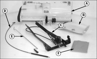
C - Welded Frame with Idlers and Belt
Bag of Parts (F) Contains:
Attaching Parts Carton Contains:
Parts in Front Lift Kit:
Parts in Mounting Kit (BM19407): LX172, LX173, LX176, LX178, LX186, and LX188 Only
Parts Ordered Separately From Your John Deere Dealer:
For Models GT262, GT242 and GT275
Assemble Chute and Welded Frame
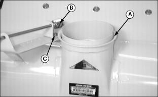
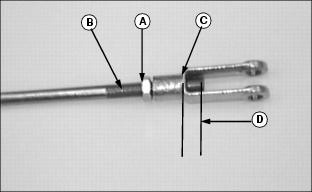
1. Apply John Deere Moly High Temperature EP Grease or an equivalent on chute base (A) and worm gear (B).
2. Loosen nut (C) and move worm gear bracket away from chute base.
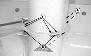
3. Fasten chute to base with three clips (D) and six M5 x 20 bolts and lock nuts (E).
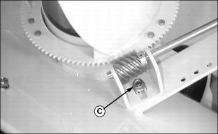
4. Move worm gear against teeth on discharge chute and tighten nut (C).
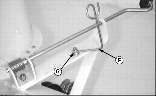
5. Fasten cable guide (F) to crank support using M8 x 25 bolt and lock nut (G).
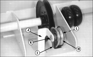
6. Install idler sheave (H) and belt guide (I) to welded support (J) using M10 x 50 bolt (K) and lock nut (L). DO NOT tighten at this time.
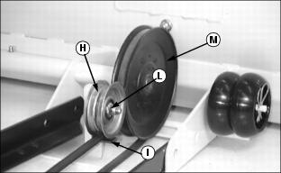
7. Slide welded frame to snowthrower and attach belt to drive sheave (M) and between idler sheave (H) and belt guide (I). Tighten nut (L).
NOTE: When tightening nuts, lift UP on opposite end of welded frame.
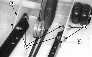
8. Lift up on rear of welded frame (N) near sheaves and fasten to snowthrower frame with four M12 x 30 hex flange bolts (O) and M12 lock nuts (P), (nuts on the inside). Tighten nuts.
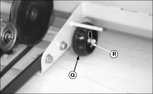
9. Install wheels (Q), one on each side of snowthrower frame, and fasten with large spring locking pin (R).
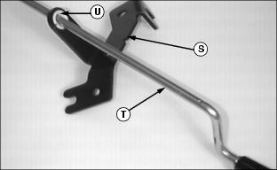
10. Slide chute and spout control bracket (S) onto chute control rod (T). Put wider flange against flat surface, and slide snap-in bearing (U) over control rod and insert snap-in bearing into bracket.
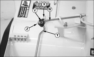
11. Install black U-joint (V) to crank support rod (W) and fasten with small spring locking pin (X).
12. Insert end of chute control rod (Y) into U-joint and fasten with small spring locking pin (Z).
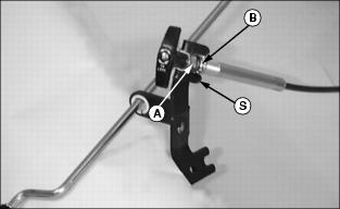
13. Thread top nut (A) on cable as far as possible.
14. Put handle end of cable into top slot of chute and spout control bracket (S) with lock washer and nut (B) next to bottom side of bracket.
15. Tighten nuts with handle in vertical position as shown.
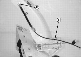
16. Route spout control cable end (C) through cable guide (F).
NOTE: Pull spout end up and extend cable assembly to longest position before installing cable on spout bracket.
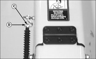
17. Put cable end (C) into upper spout bracket hole and fasten with #10 hex nut (D).
NOTE: Upper spout bracket should pivot freely.
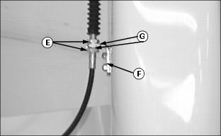
18. Loosen nuts (E). Put cable assembly into lower spout bracket (F).
NOTE: Star washers (G) are on both sides of lower spout bracket (F).
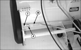
20. Install sway bar (H) on welded rod (I) and secure with large spring locking pin (J).
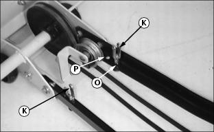
21. Fasten each yoke (K) to snowthrower frame with 3/8 x 2.5 in. bolt (L), .406 x 1.0 x .134 in. washer (M), and 3/8 in. jam nut (N) in SECOND hole (O).
NOTE: On Models LX172, LX173, LX176, LX178, LX186, LX188, LX277-AWS, GT242, GT262, and GT275: Use FIRST HOLE (P).
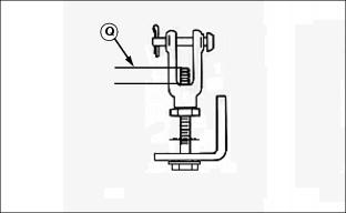
22. Adjust jam nuts until bolt exposed inside of yoke, dimension (Q), is approximately 10 -12 mm.
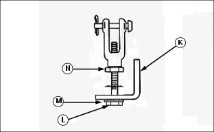
Assemble Yoke to Lift Rod
1. Turn M8 jam nut (A) onto lift rod (B).
2. Install yoke (C) on lift rod. Adjust jam nut until bolt exposed inside of yoke, dimension (D), is approximately 10 -12 mm.
Install Mounting Kit (BM19407) (On LX172, LX173, LX176, LX178, LX186, and LX188 Only)
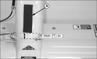
1. Position foam pad (A) on center of chute back and approximately 25 mm (1 in.) from chute base. Apply foam pad to chute.

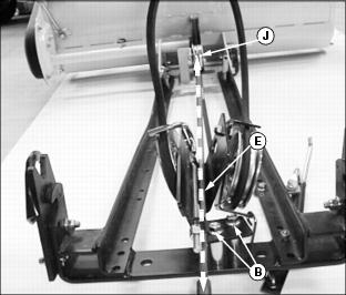
2. Remove two bolts and nuts (B) from idler support.
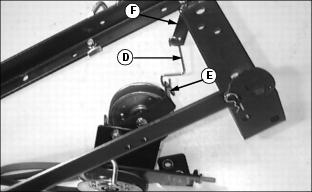
4. Attach new idler link (D) to idler support (E) and idler arm (F).
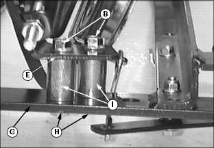
5. Fasten idler support (E) to welded frame (G) with two M10 x 60 bolts (H), spacers (I), and nuts (B), (removed from idler support in Step 2). Do not tighten at this time.
IMPORTANT: Avoid damage! Correct alignment of sheaves is critical for expected belt life. Make sure that bottom of rear idler support is in alignment with the front auger drive sheave. |
Picture Note: A straight edge is placed in the "V" to show correct alignment.
6. Move idler support so that the "V" at the bottom of the support (E) is in line with the front auger drive sheave (J).
7. Check alignment and then tighten nuts (B).
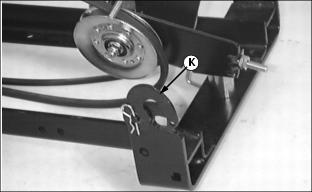
8. Remove C-shaped latch (K) from each side of welded frame.
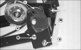
9. Fasten welded latch (L), one on each side, to welded frame with two M10 x 35 bolts (M) and M10 lock nuts (N).