![]()
Introduction
Safety Signs
Controls
Operating
Replacement Parts
Service Machine Safely
Service
Troubleshooting
Storing Machine
Assembly
Specifications
Warranty
John Deere Quality Statement
Copyright© Deere & Company

Assembly
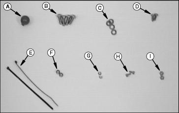
Identify Parts
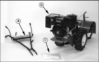
Bag of Parts
Install Handlebar Assembly
· Disconnect handlebar swivel handle from mounting hole (shipping position).
· Position handlebars to outside of mounting frame.
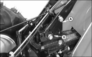
· Install two cap screws (3/8 x 1 in.)(A) with lock washers. DO NOT TIGHTEN.
· Select handlebar height and install two cap screws (3/8 x 1 in.) (B) with lock washers.
· Tighten all four cap screws (A and B).
NOTE: The swivel lock (C) can be difficult to operate due to the amount of black paint.
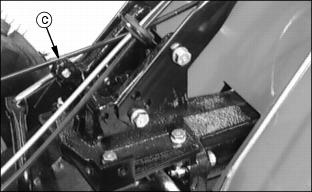
· Lubricate and remove paint as required until the swivel lock (C) operates freely.
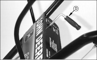
· Position handlebar swivel handle (D) as shown.
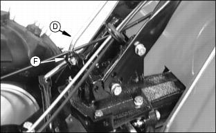
· Install handlebar swivel handle (D) into swivel lock (C) and secure with cotter pin (F).
· Check handlebar swivel for proper operation.
Connect Drive Cables
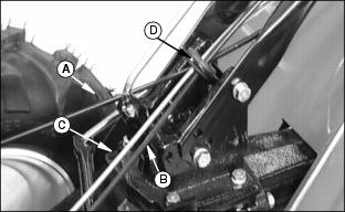
1. Make sure drive cables (A and B) and throttle cable (C) are routed through grommet (D).
2. Connect cables to handlebar bracket:
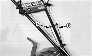
· Long cable (A) to inside of bracket. (will go to "R" Bottom Lever)
· Short cable (B) to outside of bracket. (will go to "F" Top Lever)
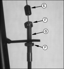
· Position cables in bracket about mid-way in threads (G).
· Secure cables to bracket by tightening nuts (F) against bracket.
· Put rubber boot (E) down over cable end. This will help to keep moisture out of cable.
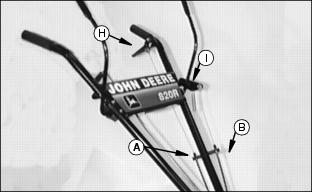
· Cable (A) to "R" Bottom Lever (H).
· Cable (B) to "F" Top Lever(I).
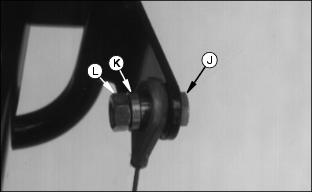
· When attaching cable ends use cap screws (1/4 x 3/4 in.) (J), cable spacers (K) and lock nuts (1/4 in.) (L).
· Tighten lock nuts, cable must be able to move freely around spacers.
4. Check for proper adjustments in the Main Clutch levers:
· "F" Top Levers - see Adjusting "Forward" Drive Belts Tension in the Service section.
· "R" Bottom Lever - see Adjusting "Reverse" Drive Belt Tension in the Service section.
Connect Throttle Assembly
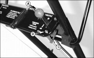
1. Position throttle assembly in handlebar bracket.
2. Use two screws (10-24)(B) and two lock nuts (3/16 in.) (C) to attach throttle.
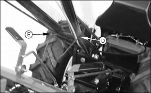
· Position tie strap (D) around handlebar and throttle cable.
· Position tie strap (E) around handlebar and drive cables.
6. Operate swivel handlebars, tie straps should not interfere with cable movement.
Check Tire Pressure
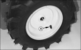
1. Tiller was shipped with tires over inflated to ensure seating of bead. Reduce tire pressure to 96 kPa (14 PSI) before operating.
Check Transmission Oil Level
1. Place tiller on a flat, level surface.
3. Oil level should be at the FULL mark on the dipstick.
Approximate transmission capacity is 1 L (36 oz.)
4. If necessary, add transmission oil. (see Transmission Oil in the Service Section for correct oil).
Remind customer to drain and refill transmission after first 25 hours of operation or at the end of first season, whichever comes first.
Check Gearbox Oil Level
1. Place tiller on a flat, level surface.
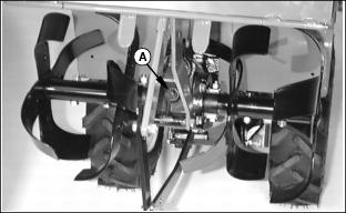
3. A correct oil level; oil should run out of filler hole or up to filler hole.
Approximate gearbox capacity is 236 mL (8 oz.)
4. If necessary, add gearbox oil. (see Gearbox Oil in the Service Section for correct oil).
Remind customer to drain and refill gearbox after first 25 hours of operation or at the end of first season, whichever comes first.
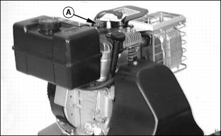
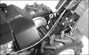
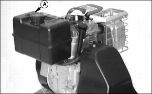
Add Engine Oil
NOTE: See Engine Oil in the Service Section for proper type of oil.

Approximate crankcase capacity is 1.3 L (44 oz.)
2. Slowly add oil into engine through engine oil fill plug (B).
3. Install dipstick, pushing it down tightly, remove it and observe oil level.
4. Add oil until oil level is at the FULL mark on the dipstick.
5. Install dipstick (A)oil fill plug (B).
Remind customer to change oil in engine crankcase after first 2 hours of operation.
Fill Fuel Tank Safely
Add Fuel
2. DO NOT fill tank to top; fuel can expand.
Connect Spark Plug
1. Remove "IMPORTANT" shipping tag.