![]()
Introduction
Safety Signs
Controls
Operating
Replacement Parts
Service Machine Safely
Service
Engine Warranty Maintenance Statement
Cleaning / Changing Air Cleaner
Cleaning and Gapping Spark Plug
Changing "Forward" Drive Belts
Adjusting "Forward" Drive Belts Tension
Adjusting "Reverse" Drive Belt Tension
Checking Transmission Oil Level
Checking Tiller Gearbox Oil Level
Lubricating Drive Idler Sheaves
Troubleshooting
Storing Machine
Assembly
Specifications
Warranty
John Deere Quality Statement
Copyright© Deere & Company

Service
Engine Warranty Maintenance Statement
Maintenance, repair, or replacement of the emission control devices and systems on this engine, which are being done at the customers expense, may be performed by any nonroad engine repair establishment or individual. Warranty repairs must be performed by an authorized John Deere dealer.
Service Intervals
· Change transmission oil. (after initial purchase) |
|
|
· Clean engine cylinder cooling fins. · Check transmission oil level. |
|
Service Record
Service Record
Engine Oil

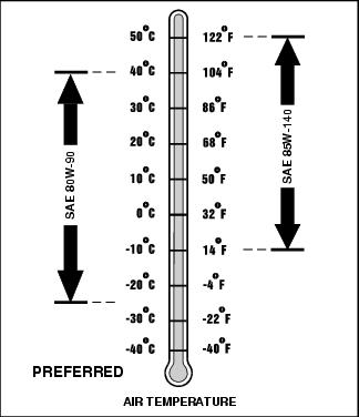
Use oil viscosity based on the expected air temperature range during the period between oil changes.
The following John Deere oils are PREFERRED:
The following John Deere oils are also recommended, based on their specified temperature range:
Other oils may be used if above John Deere oils are not available, provided they meet one of the following specifications:
· SAE 30-API Service Classification SC or higher;
· SAE 5W-30-API Service Classification SG or higher;
· SAE 10W-30-API Service Classification SG or higher.
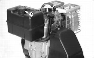
Checking Engine Oil Level
IMPORTANT: Avoid damage! Oil level MUST be maintained in a safe operating range on dipstick at all times or engine damage will result. |
Service Interval: Check oil level daily or every five hours of operation.
1. Park tiller on a flat level surface, stop engine and disengage clutches.
2. Wipe all debris from around dipstick.
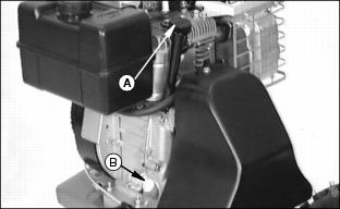
3. Remove dipstick (A) and wipe it clean.
4. Install dipstick, pushing it down tightly, remove it and observe oil level.
· Oil level must be between ADD and FULL marks on dipstick.
NOTE: See Engine Oil in this section for proper type of oil.
· If necessary add clean fresh engine oil through engine oil fill plug (B) until oil level is at the FULL mark on the dipstick.
· Approximate crankcase capacity is 1.3 L (44 oz.)
· DO NOT over fill. Level must not exceed FULL mark.
5. Install dipstick and oil fill plug.
Changing Engine Oil
Service Interval: Change engine oil after first 2 hours of operation, thereafter change oil every 25 hours of operation or yearly.
1. Run engine just prior to changing oil. Oil will flow more freely and carry away more contamination when warm.
2. Park tiller on a flat level surface, stop engine and disengage clutches.
· Position a drain pan under engine.
· After engine oil has completely drained, install oil drain plug.
NOTE: See Engine Oil in this section for proper type of oil.
· Add clean fresh engine oil through engine oil fill plug (B).
· Approximate crankcase capacity is 1.3 L (44 oz.).
· Wipe all debris from around dipstick.
· Remove dipstick (A) and wipe it clean.
· Install dipstick, pushing it down tightly, remove it and observe oil level.
· Oil level must be between ADD and FULL marks on dipstick.
· If necessary, add oil until oil level is at FULL mark on dipstick.
· DO NOT over fill. Level must not exceed FULL mark.
· Install dipstick and oil fill plug.
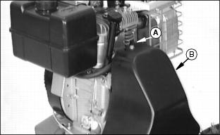
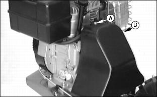
Cleaning / Changing Air Cleaner
· Filter Precleaner: Washed every 25 hours of operation or yearly, or more often under extremely dirty, dusty conditions.
· Filter Element: Inspect every 5 hours of operation and replace if damaged or dirty. Check more frequently under extremely dirty, dusty conditions.
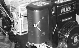
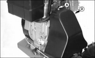
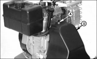
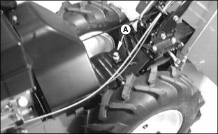
· Loosen two screws (A). Screws will not come out, just loosen.
· Remove air cleaner cover assembly(B).
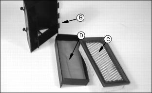
· Check filter element and tap lightly to remove light dust.
· Examine element carefully and replace if bent, crushed, damaged or dirty.
· Wash in warm water with detergent. Rinse thoroughly until all traces of detergent are eliminated and squeeze (don't wring) away excess water. Air dry.
· Soak in fresh, clean engine oil and squeeze out excess oil.
4. Assemble and install filter assembly.
Cleaning and Gapping Spark Plug
Service Interval: Check spark plug every 100 hours of operation or yearly.
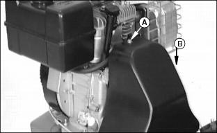
1. Clean area around spark plug.

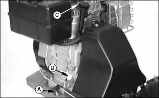
2. Disconnect spark plug wire (A).
3. Remove and inspect spark plug:
· Clean plug and check for damage, replace if necessary.
· If plug is in good condition, check gap.
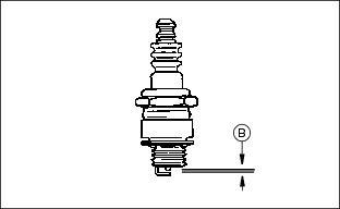
4. Check and adjust spark plug gap (B):
5. Install spark plug and tighten to 20 N·m (15 lb-ft.).
Cleaning Cylinder Fins
Service Interval: Clean cylinder fins every 50 hours of operation or yearly, or more often under extremely dirty, dusty conditions.
This engine is air cooled. Air must circulate freely around engine from air intake screen, and over cooling fins on cylinder head and block, to prevent overheating.
Remove cooling shrouds and clean engine fins. Also clean external surfaces of engine of dust, dirt and oil deposits which can contribute to improper cooling.
IMPORTANT: Avoid damage! DO NOT run engine with cooling shrouds removed. This will cause overheating and engine damage. |
Adjusting Carburetor
NOTE: The carburetor is calibrated by the engine manufacturer and should not require any adjustments.
If engine is operated at altitudes above 1829 m
(6,000 ft.), some carburetors may require a special high altitude main jet. See your John Deere dealer.
Possible engine surging will occur at high rpm when the machine is in neutral ("N") and the tines are disengaged. This is a normal condition due to the emission control system.
If engine is hard to start or runs rough, check the TROUBLESHOOTING section of this manual.
After performing the checks in the troubleshooting section and your engine is still not performing correctly, contact your John Deere dealer.
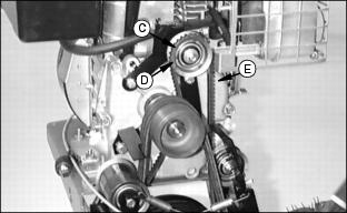
Adjusting Tine Clutch
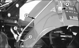
The tine clutch is used to engage the tiller tines. When you move tine clutch lever (A) forward (over center) to the "IN" position the tines will engage and start to rotate. Move Tine clutch lever (A) rearward (over center) to the "OUT" position the tines will disengage and stop rotating.
The tine clutch lever (A) should shift smoothly and with minimum effort. As the clutch wears it may be necessary to adjust the linkage to maintain this minimum effort, smooth shift.
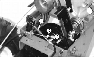
· Disconnect quick coupler (D) from gearbox shift arm.
· Tighten or loosen coupler (D), this will change the length of linkage rod (B).
· Install quick coupler and tighten nut.
· Operate tine clutch lever, the lever should shift smoothly and with minimum effort. Repeat the above steps as needed.
Changing "Forward" Drive Belts
1. Remove cap screw (A) and belt cover (B).
2. Remove reverse drive belt (C). (See Changing "Reverse" Drive Belt in this section.)
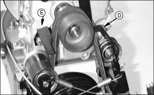
3. Remove wingnut and belt guide (D).
4. Loosen cap screw and move belt guide (E) out of the way.
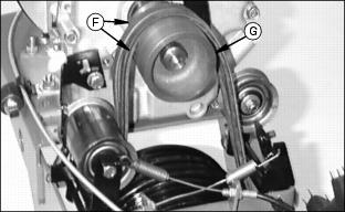
5. Remove both forward drive belts (F) from drive sheave (G) and from around lower driven sheave (gearbox input sheave).Inspect belts and replace if necessary.
6. Install (new) forward drive belt around lower driven sheave (gearbox input sheave) and around drive sheave (G).
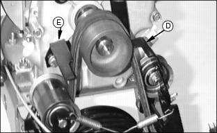
7. Install belt guide (D) and wingnut.
8. Reposition belt guide (E) and tighten cap screw.
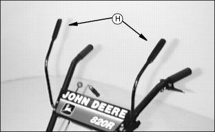
9. Hold main clutch "F" Top Levers (H) in the engaged position. This will tighten both drive belts.
10. Check belt guide clearance:
· Measure clearance between drive belts and belt guides.
· Clearance should be approximately 1.5 to 3 mm (1/16 to 1/8 in.).
11. Adjust belt tension. (See Adjusting "Forward" Drive Belt Tension in this section.)
12. Install reverse drive belt (C). (See Changing "Reverse" Drive Belt in this section.)
13. Install belt cover and cap screw.
Adjusting "Forward" Drive Belts Tension
1. Remove cap screw (A) and belt cover (B).
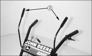
2. Operate and hold main clutch "F" Top Levers (C) in the engaged position.
IMPORTANT: Avoid damage! When adjusting belt tension do not tighten cable so much that the engagement spring (D) is expanded 19 mm (3/4 in.) longer than it's relaxed state length. |
NOTE: Cable length can be adjusted at either end, it is suggested to adjust cable on the handlebar end first.
· Tighten or loosen nut (F) until the engagement spring (D) has expanded in length approximately
6 mm (1/4 in.) from it's relaxed state length.
If belts have stretched too much and tension cannot be adjusted, install new belts.
4. Install belt cover and cap screw.
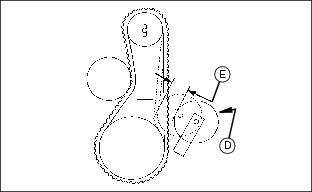
Changing "Reverse" Drive Belt
1. Remove cap screw (A) and belt cover (B).
3. Idler (D) is mounted in an adjustment slot. Slide idler down to loosen drive belt tension.
4. Remove reverse drive belt (E) from around idler (D) and from around lower driven sheave (gearbox input sheave).
5. Inspect belt and replace if necessary.
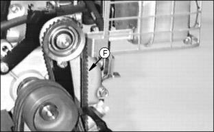
NOTE: The reverse drive belt is a cogged belt. Install belt with cogs (rough edge) (F) to the outside as shown.
6. Install (new) reverse drive belt around lower driven sheave (gearbox input sheave) and around idler (D).
7. Move idler (D) up to put tension on drive belt.
9. Adjust belt tension. (See Adjusting "Reverse" Drive Belt Tension in this section.)
10. Install belt cover and cap screw.
Adjusting "Reverse" Drive Belt Tension
1. Remove cap screw (A) and belt cover (B).
2. Operate main clutch "R" bottom lever (C).
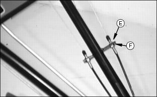
3. Observe belt tension idler (D) movement. When belt tension and cable pull are properly adjusted, the belt tension idler will have approximately 32 mm (1 1/4 in.) of travel (E) between neutral and the fully engaged position.
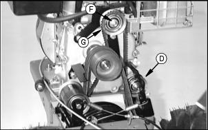
· Idler (G) is mounted in an adjustment slot. Slide idler up or down to change belt tension.
· Repeat steps 2 and 3 until belt tension is properly adjusted.
IMPORTANT: Avoid damage! When adjusting cable pull do not tighten cable so much that the engagement spring (H) is expanded 19 mm (3/4 in.) longer than it's relaxed state length. |
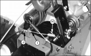
NOTE: Cable length can be adjusted at either end, it is suggested to adjust cable on the handlebar end first.
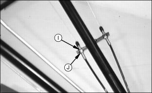
· Tighten or loosen nut (J) until the engagement spring (H) has expanded in length approximately 6 mm (1/4 in.) from it's relaxed state length.
6. Repeat steps 2, 3, 4 and 5 until the belt tension and cable pull are adjusted properly.
If belt has stretched too much and tension cannot be adjusted, install a new belt.
7. Install belt cover and cap screw.
Checking Tire Pressure

Check tire pressure with an accurate gauge.
· Tire pressure should be 96 kPa (14 PSI).
Gear Oil
Use oil viscosity based on the expected air temperature range during the period between oil changes.
The following John Deere gear case oil is PREFERRED:
The following John Deere gear case oil is also recommended if above preferred oil is not available:
Other gear case oils may be used if above recommended John Deere gear case oils are not available, provided they meet the following specification:
· API Service Classification GL-5.
Checking Transmission Oil Level
IMPORTANT: Avoid damage! Serious damage can be caused to your transmission if it is allowed to run for even a short time without proper amount of oil. |
Service Interval: Check transmission oil level every 5 hours of operation or at start of tilling season (yearly).
1. Place tiller on a flat, level surface.
· Wipe all debris from around dipstick (A).
· Remove dipstick and observe oil level.
· Oil level must be to FULL mark on dipstick.
· If necessary, add oil until oil level is at FULL mark on dipstick. (see Gear Oil in this section for correct oil).
· DO NOT over fill. Level must not exceed FULL mark.
· Install and tighten dipstick.
Changing Transmission Oil
Service Interval: Drain and refill transmission after first 25 hours of operation or at the end of first season, whichever comes first, thereafter change oil only if repair parts are installed or you see contaminant's in the oil.
1. Run engine and tiller just prior to changing oil. Oil will flow more freely and carry away more contamination when warm.
2. Place tiller on a flat, level surface.
· Place a shallow drain pan below drain plug (B).
· After oil has completely drained, install oil drain plug securely.
· Wipe all debris from around dipstick (A).
NOTE: See Gear Oil in this section for proper type of oil.
· Add clean fresh oil through dipstick hole.
· Approximate transmission capacity is 1 L (36 oz.).
· Install and remove dipstick and observe oil level.
· Oil level must be to FULL mark on dipstick.
· If necessary, add oil until oil level is at FULL mark on dipstick.
· DO NOT over fill. Level must not exceed FULL mark.
· Install and tighten dipstick.
Checking Tiller Gearbox Oil Level
IMPORTANT: Avoid damage! Serious damage can be caused to your gearbox if it is allowed to run for even a short time without proper amount of oil. |
Service Interval: Check gearbox oil level every 5 hours of operation or at start of tilling season (yearly).
1. Place tiller on a flat, level surface.
· Wipe all debris from around plug (A).
· A correct oil level; oil should run out of filler hole or up to filler hole.
· If necessary, add oil. (see Gear Oil in this section for correct oil).
Changing Gearbox Oil
Service Interval: Drain and refill gearbox after first 25 hours of operation or at the end of first season, whichever comes first, thereafter change oil only if repair parts are installed or you see contaminant's in the oil.
1. Run engine and tiller just prior to changing oil. Oil will flow more freely and carry away more contamination when warm.
2. Place tiller on a flat, level surface.
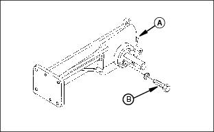
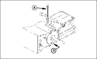
· Place a shallow drain pan below one lower cap screw and lock washer (B) that mounts bearing flange.
· Remove cap screw and lock washer (B).
· After oil has completely drained, install cap screw and lock washer securely.
· Wipe all debris from around plug (A).
NOTE: See Gear Oil in this section for proper type of oil.
· Add clean fresh oil through plug hole (A).
· Approximate gearbox capacity is 236 mL (8 oz.).
· Wipe all debris from around plug (A).
· A correct oil level; oil should run out of filler hole or up to filler hole.
Lubricating Handlebar Swivel
IMPORTANT: Avoid damage! DO NOT over lubricate or use grease on the handlebar swivel mechanism. Dirt and dust will tend to collect on any exposed lubricated parts. |
Service Interval: Lubricate handlebar swivel as needed.
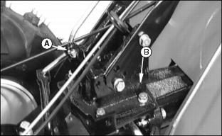
Handlebar Swivel Lock (A): Lightly oil locking pivot. Lock should easily be unlocked from operator's station and should return by spring force. Wipe off any excess oil.
Handlebar Swivel (B): Lightly oil swivel base. Handlebars should swivel smoothly and with little effort. Wipe off any excess oil.
Lubricating Drive Wheels
Service Interval: Lubricate drive wheel axles on a yearly basis.
1. Raise and support tiller so that drive wheels are off the ground.
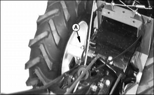
2. Remove locknut and bolt (A).
4. Lubricate axle and inside of drive wheel hub with a general purpose grease or oil. This lubrication is to prevent rusting and seizing.
5. Install drive wheels with traction ARROW pointing forward as shown on the tire sidewall.
6. Install and tighten hardware.
Lubricating Tine Shafts
Service Interval: Lubricate tine shafts on a yearly basis.
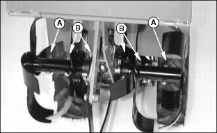
1. Remove locknuts and bolts (A) to remove outer tines.
1. Remove locknuts and bolts (B) to remove inner tines.
2. Lubricate tine shafts and inside of tine hubs with a general purpose grease or oil. This lubrication is to prevent rusting and seizing.
3. Install tines with the cutting edges pointing towards the front of the tiller.
4. Install and tighten hardware.
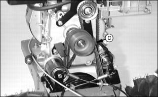
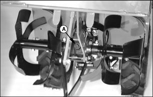
Lubricating Drive Idler Sheaves
Service Interval: Lubricate drive idler sheaves every 25 hours of operation or yearly, or more often under extremely dirty, dusty conditions.
1. Remove cap screw (A) and belt cover (B).
2. Lightly oil bearings on (forward drive belt) idler sheave and idler arm pivots (A).
· Idler sheave should spin freely.
· Idler arm should pivot smoothly and return to the disengaged position by spring force.
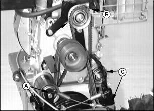
3. Lightly oil bearings on (reverse drive belt - stationary idler) idler sheave (B).
· Idler sheave should spin freely.
4. Lightly oil bearings on (reverse drive belt) idler sheave and idler arm pivots (C).
· Idler sheave should spin freely.
· Idler arm should pivot smoothly and return to the disengaged position by spring force.
5. Install belt cover and cap screw.
Fuel
IMPORTANT: Avoid damage! Avoid spilling fuel. Fuel can damage plastic and painted surfaces. DO NOT mix oil with gasoline. Unleaded gasoline with an octane rating of 87 or higher is recommended. |
· Use only clean, fresh, unleaded regular grade gasoline.
· Remove any trash from top of fuel tank drain area.
· Use summer blended fuel for warm weather operation and winter blended fuel for cold weather.
· Never use fuel that is stale or has been stored for a long period of time:
Warm Weather - Maximum 60 days.
Cold Weather - Maximum of 90 days.
· Fill fuel tank at the end of each day's operation. This helps to keep condensation out of fuel tank.
Oxygenates (either ethanol or MTBE) are added to the gasoline. If you use the oxygenated fuel be sure it is unleaded and meets the minimum octane rating requirement.
The following are the EPA approved percentages of fuel oxygenates:
ETHANOL (Ethyl or Grain Alcohol): You may use gasoline containing up to 10 percent ethanol by volume.
MTBE (Methyl Tertiary Butyl Ether): You may use gasoline containing up to 15 percent MTBE by volume.
METHANOL (Methyl or Wood Alcohol): You may use gasoline containing up to 5 percent methanol by volume, as long as it also contains cosolvents and corrosion inhibitors to protect the fuel system. Gasoline containing more than 5 percent methanol by volume may cause starting and/or performance problems. It may also damage metal, rubber, and plastic parts of your fuel system.
1. STOP engine. Allow engine to cool for two several minutes before refueling.
Approximate fuel tank capacity 3.8 L (4 Qts.)