Introduction
Safety Signs
Controls
Operating
Service Machine Safely
Service
Troubleshooting
Storing Machine
Assembly
Check Auger and Traction Drive Cables
Specifications
Warranty
John Deere Quality Statement
CopyrightŠ Deere & Company

Assembly
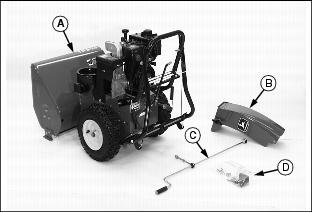
Identify Snowblower Parts
Bag Of Parts
NOTE: ˇ Two ignition keys are supplied with this snowblower. They are attached to the engine choke knob.
ˇ Retain the two extra shear bolts that are provided in the bag of parts. See Replacing Shear Bolt in the Service section.
Adjustments
Parts of the snowblower have been removed or disconnected for shipping. These parts must be installed or connected, but do not have to be adjusted. Your snowblower has been adjusted at the factory.
Install these parts and check the adjustments.
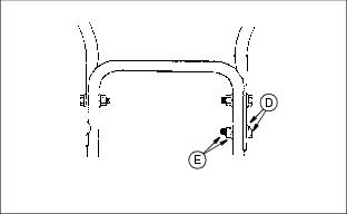
Assemble Handlebars
IMPORTANT: Avoid damage! Be sure not to disconnect cable springs (A). Make sure the cables are not caught between the upper and lower handle. |
1. Remove packing material and three tie straps.
2. Loosen, but DO NOT remove the bolts, flat washers, lockwashers, and hex nuts (B) and (C) in the upper holes of the lower handle.
3. Raise upper handle into operating position. Upper handle should be to the outside of the lower handle.
4. Install one 5/16 x 2 in. cap screw and flat washer (D), and lock washer and hex nut (E) into right lower hole of upper handle. DO NOT tighten until all bolts are in place and chute crank is attached. (See Install Chute Crank below.)
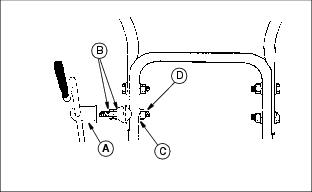
Install Chute Crank
1. Locate the crank assembly removed from carton earlier and remove the 3/8 in. nylon lock nut and flat washer from the eye bolt assembly (A).
2. Check to make sure the two 3/8 in. jam nuts (B) are tight.
3. Insert the eye bolt assembly
into the left lower hole and
fasten with 3/8 in. flat washer (C) and the 3/8 in. nylon locknut (D) previously removed.
4. Tighten nut on eye bolt, keeping eye bolt in line with the rod while tightening the inside securely.
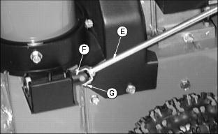
5. Fasten chute control rod (E) to chute crank yoke (F) with drilled pin and cotter pin (G).
NOTE: Be sure crank does not touch carburetor cover.
6. TIGHTEN ALL four handle bolts.
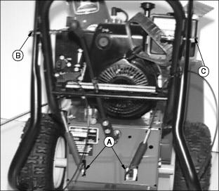
Check Auger and Traction Drive Cables
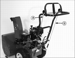
Check the traction drive cable (A) and the auger drive cable (B). Both cables must have the cable "Z" ends connected at the hand controls and spring ends connected on the control levers.
Install Gear Shift Knob
IMPORTANT: Avoid damage! To hold shift knob securely and to prevent it from falling off, install hex nut and shift knob with maximum thread engagement. |
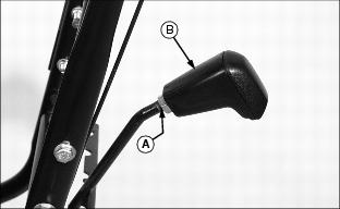
1. Install 1/2 in. hex nut (A) onto shift rod. Install hex nut as far as it will go.
2. Install shift knob (B) onto shift rod. Install shift knob until it bottoms on the hex nut.
3. Rotate shift knob to the desired position and tighten hex nut up against knob to hold it securely.
Install Chute
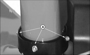
1. Align three holes in discharge chute with holes in blower housing.
2. Install three 5/16 x 1in. carriage bolts, placing carriage bolt heads to the INSIDE of chute.
3. Fasten with three flat washers and 5/16 in. lock nuts (A).
4. Tighten lock nuts. DO NOT overtighten.
Check Tire Pressure
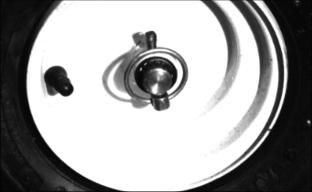
Tire pressure in each tire should be 110 kpa (15 psi).
Adjust Skid Height
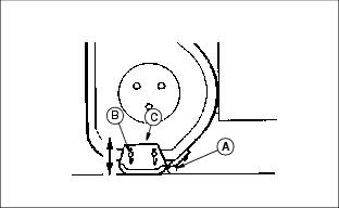
1. Place an extra shear bolt (A) (from the bag of parts) under each end of the scraper blade (to act as a spacer). Do not put bolt under the skid.
2. Loosen two nuts (B) and push skid (C) up or down until it touches the ground and the scraper blade is resting on the shear bolt. Tighten nuts.
Add Engine Oil
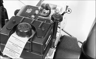
IMPORTANT: Avoid damage! Snowblower is shipped without oil in engine. Oil must be added before running engine. |
2. Add 0.6 L (19 oz) of oil through dipstick tube. (See Gear Oil in Service section for correct oil.)
ˇ Install and tighten dipstick.
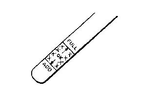
ˇ Remove dipstick. Check oil level. Oil should be between ADD and FULL marks on dipstick.

