Introduction
Safety Signs
Controls
Operating
Service Machine Safely
Service
Engine Warranty Maintenance Statement
Adjusting Traction and Auger Drive Cable
Troubleshooting
Storing Machine
Assembly
Specifications
Warranty
John Deere Quality Statement
Copyright© Deere & Company

Service
Engine Warranty Maintenance Statement
Maintenance, repair, or replacement of the emission control devices and systems on this engine, which are being done at the customers expense, may be performed by any nonroad engine repair establishment or individual. Warranty repairs must be performed by an authorized John Deere dealer.
Service Intervals
|
· Lubricate friction disk hub zerk. |
Service Record
Avoid Fumes
· If it is necessary to run an engine in an enclosed area, use an exhaust pipe extension to remove the fumes. |
Engine Oil
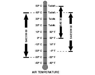
Use oil viscosity based on the expected air temperature range during the period between oil changes.
The following John Deere oil is preferred:
The following John Deere oils are also recommended, based on their specified temperature range:
Other oils may be used if above John Deere oil is not available, provided they meet one of the following specifications:
· SAE 5W-30-API Service Classification SG or higher
· SAE 10W-30-API Service Classification SG or higher
SAE 30-API Service Classification SC or higher
Grease
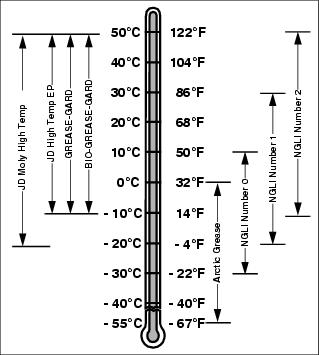
Use grease based on the expected air temperature range during the service interval.
The following greases are preferred:
· John Deere Moly High Temperature EP Grease.
· John Deere High Temperature EP Grease.
Other greases may be used are:
· SAE Multipurpose EP Grease with 3 to 5 percent molybdenum disulfide.
· Greases meeting Military Specification MIL-G-10924C may be used as arctic grease.
Checking Engine Oil
1. Park snowblower on a level surface.
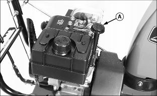
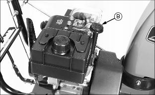
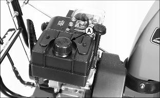
2. Remove dipstick (A). Wipe it.
· Install and tighten dipstick.
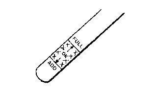
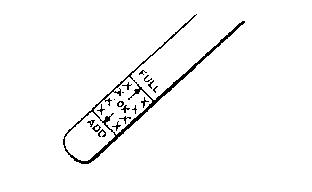
· Remove dipstick. Check oil level. Oil should be between ADD and FULL marks on dipstick.
4. Add oil if necessary. (See Engine Oil in this section for correct oil.)
5. Install and tighten dipstick.
Changing Engine Oil
NOTE: If you do not operate snowblower 25 hours during season, change oil at end of season.
1. Park snowblower on a level surface.
2. Run engine a few minutes to warm oil.
6. Drain oil into container. Install drain cap.
7. Add 0.6 L (19 oz) of oil through dipstick tube. (See Engine Oil in this section).
8. Install and tighten dipstick.
9. Remove dipstick. Check oil level. Oil should be between ADD and FULL marks on dipstick.
10. Install and tighten dipstick.
Gapping Spark Plug
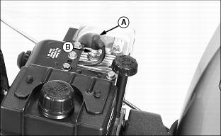
1. Disconnect spark plug wire (A). Remove plug (B).
2. Inspect plug for wear or damage. Replace plug if needed.
3. Adjust gap: 0.76 mm (0.030 in.).
4. Install and tighten plug to 27 N·m (20 lb-ft).
Cleaning Fuel Cap Vents
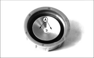
2. Clean vents (A) in nonflammable solvent.
Adjusting Carburetor
NOTE: The carburetor is calibrated by the engine manufacturer and should not require any adjustments.
If engine is operated at altitudes above 1829 m
(6,000 ft.), some carburetors may require a special high altitude main jet. See your John Deere dealer.
Possible engine surging will occur at high rpm when the machine is in neutral ("N") and the auger is disengaged. This is a normal condition due to the emission control system.
If engine is hard to start or runs rough, check the TROUBLESHOOTING section of this manual.
After performing the checks in the troubleshooting section and your engine is still not performing correctly, contact your John Deere dealer.
Checking Gearbox Lubricant
Auger gearbox has been lubricated at factory and SHOULD NOT require additional lubrication.
If for some reason the lubricant should leak out, or if the auger gearbox has been serviced; check lubricant.
2. If you cannot see grease, use a wire or plastic tie strap to check for grease.
· If you can see grease on wire or tie strap, do not add grease.
3. If necessary, add John Deere High Temperature EP Grease 100 gr (3-1/2 oz) maximum when gearbox is empty or an equivalent, such as:
Adjusting Auger Drive Belt
IMPORTANT: Avoid damage! Before adjusting belt, check auger drive cable adjustment. (See Adjusting Auger Drive |
NOTE: If you do not operate snowblower 25 hours during season, adjust auger drive belt at end of season.
1. Disconnect spark plug wire.
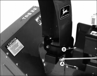
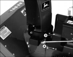
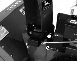
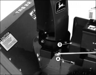
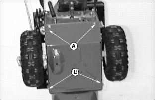
2. Loosen screw (A) on each side of belt cover (B). Remove cover.
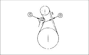
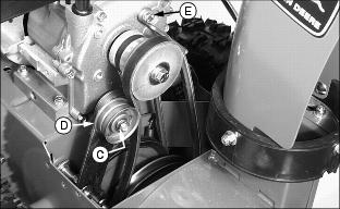
3. Hold down auger drive lever so idler pulley (C) is engaged. Check belt deflection. Belt should deflect 13 mm (1/2 in.) (D) with moderate thumb pressure.
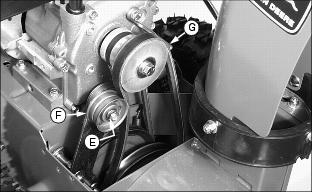
· Loosen nut (E). Move pulley (F) toward belt 3 mm (1/8 in.).
5. Check belt guides (G) adjustment. (See Adjusting Belt Guides in this section.)
Adjusting Belt Guides
1. Disconnect spark plug wire.
2. Loosen screw (A) on each side of cover (B). Remove cover.
3. Hold auger drive control lever down to handle.
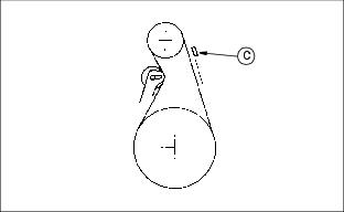
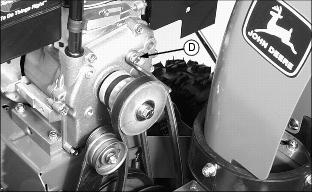
4. Measure distance between belt guide (C) and belt. Distance should be 3 mm (3/32 in.). If it is not, loosen guide mounting bolt (D), adjust guide, and tighten bolt.
5. Release control lever. Install cover. Connect plug wire.
Replacing Auger Drive Belt
1. Disconnect spark plug wire.
2. Loosen screw (A) on each side of cover (B). Remove cover.
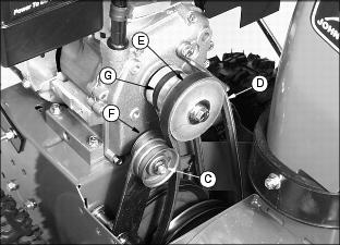
3. Loosen nut (C). Move pulley (D) away from belt.
4. Loosen belt guides (E). Move them away from belt.
5. Remove belt (F) from engine drive pulley (G).
6. Remove top two housing bolts (H), and loosen bottom two bolts (I). Separate auger housing from engine frame hinging on bottom 2 bolts.
7. Remove brake arm (J) from housing. DO NOT remove spring.
9. Position new belt on auger pulley.
10. Install brake arm. Be sure brake arm is pushed into housing, and brake pad is seated in pulley groove.
11. Position belt onto engine drive pulley.
12. Install auger housing to engine frame with top two bolts. Tighten bottom two bolts.
13. Adjust belt. (See Adjusting Auger Drive Belt in this section.)
14. Adjust belt guides. (See Adjusting Belt Guides in this section.)
15. Install cover. Connect plug wire.
16. Check auger drive cable adjustment. (See Adjusting Auger And Traction Drive Cable in this section.)
Replacing Traction Drive Belt
1. Disconnect spark plug wire.
2. Loosen screw (A) on each side of cover (B). Remove cover.
3. Loosen belt guides. Move them away from belt.
4. Loosen nut (C) and move pulley away from auger drive belt (D).
5. Take auger drive belt off of engine pulley (E).
6. Pull and hold idler pulley (F) away from traction drive belt (G). Pull belt past pulley.
7. Remove belt from engine pulley.
8. Remove belt from between bottom of large pulleys.
9. Install new belt on bottom of large pulley and onto engine pulley.
10. Pull idler pulley toward you and slip belt past pulley.
12. Install auger drive belt on engine pulley.
13. Adjust auger drive belt pulley. (See Adjusting Auger Drive Belt in this section.)
14. Adjust belt guides. (See Adjusting Belt Guides in this section.)
15. Install cover. Connect plug wire.
16. Check traction drive cable adjustment. (See Adjusting Traction And Auger Drive Cable in this section.)
Adjusting Friction Wheel
If necessary, have another person help you stand snowblower on end. |
NOTE: Do this service when there is only a small amount of fuel in fuel tank.
1. Move speed selector lever to first (1) speed.
2. Stand snowblower on end of auger housing.
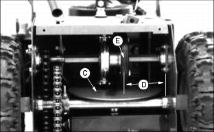
4. Check position of friction wheel. Right side of disc drive plate (C) should be 76 mm (3 in.) (D) from center of friction wheel (E).
5. To adjust position of friction wheel:
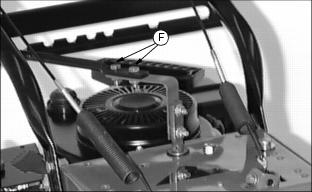
· Loosen two nuts (F) on speed selector lever.
· Move friction wheel to proper position.
· When position is correct, tighten nuts.
Replacing Shear Bolt
NOTE: Two extra shear bolts are in the bag of parts included with your snowblower.
2. Remove broken shear bolt (A), if necessary.
3. To help prevent auger from rusting, lubricate auger shaft at two shear bolt points and at end of each shaft with a lightweight oil. Turn auger on shaft several turns to help distribute oil.
4. Line up holes in auger with hole in auger shaft.
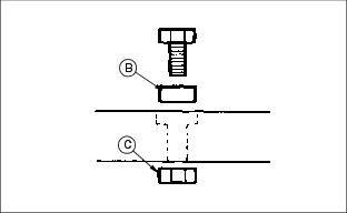
5. Install new bolt with spacer (B) under bolt head. Fasten bolt with lock nut (C).
Reversing Scraper Blade
When edge of blade is worn, rough, or bent, reverse blade.
1. Raise snowblower. Put blocks under it.
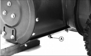
2. Remove five nuts (A), lock washers, and bolts.
3. Reverse blade. Install and tighten hardware.
Adjusting Traction and Auger Drive Cable
IMPORTANT: Avoid damage! Also adjust traction and auger drive cables whenever belts are adjusted or replaced. |
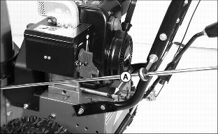
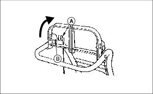
· Pull on spring and remove cable end (Z fitting) (A) from bracket hole.
· Push control lever all the way forward so it contacts the plastic bumper.
· Pull cable straight and put end of cable-the Z fitting- on top of hole.
· Center of Z fitting should be between center and top of hole (B).
· Pull threaded end of cable out of spring.
· Turn nut (C) to adjust cable to correct length.
· Install cable end in bracket hole.
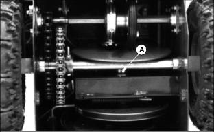
Lubricating Friction Disc Hub
Lubricate friction disc hub zerk (A) with one or two shots of John Deere Moly High Temperature EP Grease or an equivalent. (See Grease in this section.)
Lubricate Auger Shaft
NOTE: If you do not operate snowblower 25 hours during season, lubricate auger shaft at the end of the season before storage.
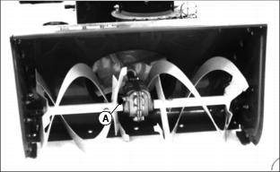
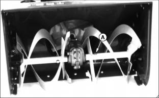
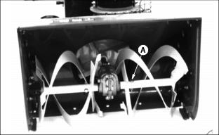
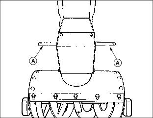
Remove two shear bolts (A). To help prevent auger from rusting, lubricate auger shaft at two shear bolt points and at the end of each shaft with a lightweight oil. Turn auger on shaft several turns to help distribute oil.
Lubricate Wheel Axle
NOTE: Do this service when there is only a small amount of fuel in fuel tank.
1. Stand snowblower on end of auger housing.
3. Lubricate both axles (A) with John Deere Moly High Temperature EP Grease or an equivalent. (See Grease in this section.)
Filling Fuel Tank Safely
IMPORTANT: Avoid damage! Avoid spilling fuel. Fuel can damage plastic and painted surfaces. DO NOT mix oil with gasoline. Unleaded gasoline with an octane rating of 87 or higher is recommended. |
· Use only clean, fresh, unleaded regular grade gasoline.
· Remove any trash from top of fuel tank drain area.
· Use summer blended fuel for warm weather operation and winter blended fuel for cold weather.
· Never use fuel that is stale or has been stored for a long period of time:
Warm Weather - Maximum 60 days.
Cold Weather - Maximum of 90 days.
· Fill fuel tank at the end of each day's operation. This helps to keep condensation out of fuel tank.
Oxygenates (either ethanol or MTBE) are added to the gasoline. If you use the oxygenated fuel be sure it is unleaded and meets the minimum octane rating requirement.
The following are the EPA approved percentages of fuel oxygenates:
ETHANOL (Ethyl or Grain Alcohol): You may use gasoline containing up to 10 percent ethanol by volume.
MTBE (Methyl Tertiary Butyl Ether): You may use gasoline containing up to 15 percent MTBE by volume.
Filling Fuel Tank
1. STOP engine. If engine is hot let it cool several minutes before you add fuel.
3. Fill fuel tank to 13 mm (1/2 in.) below bottom of filler neck to allow room for gasoline to expand.

