![]()
Introduction
Safety Signs
Controls
Operating
Replacement Parts
Service Machine Safely
Service Interval Chart
Service
Engine Warranty Maintenance Statement
Cleaning And Gapping Spark Plug
Adjusting Auger Drive Belt Tension
Checking Clutch / Impeller Brake
Adjusting Chute Deflector Lever
Adjusting Traction Drive Clutch
Adjusting Speed / Shift Linkage
Troubleshooting
Storing Machine
Assembly
Specifications
Warranty
John Deere Quality Statement
Copyright© Deere & Company

Service
Engine Warranty Maintenance Statement
Maintenance, repair, or replacement of the emission control devices and systems on this engine, which are being done at the customers expense, may be performed by any nonroad engine repair establishment or individual. Warranty repairs must be performed by an authorized John Deere dealer.
Avoid Fumes
· If it is necessary to run an engine in an enclosed area, use an exhaust pipe extension to remove the fumes. |
Engine Oil
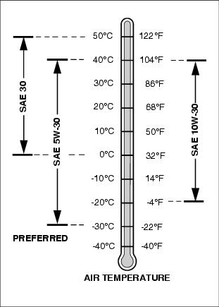
Use oil viscosity based on the expected air temperature range during the period between oil changes.
The following John Deere oils are PREFERRED:
The following John Deere oils are also recommended, based on their specified temperature range:
Other oils may be used if above John Deere oils are not available, provided they meet one of the following specifications:
· SAE 30-API Service Classification SC or higher;
· SAE 5W-30-API Service Classification SG or higher;
· SAE 10W-30-API Service Classification SG or higher.
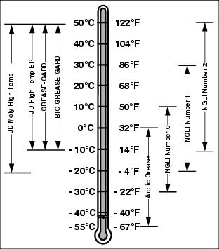
Grease
Use grease based on the expected air temperature range during the service interval.
The following greases are preferred:
· John Deere Moly High Temperature EP Grease.
· John Deere High Temperature EP Grease.
Other greases may be used are:
· SAE Multipurpose EP Grease with 3 to 5 percent molybdenum disulfide.
· Greases meeting Military Specification MIL-G-10924C may be used as arctic grease.
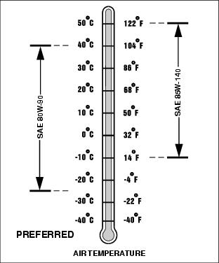
Gear Oil
Use oil viscosity based on the expected air temperature range during the period between oil changes.
The following John Deere gear case oil is PREFERRED:
The following John Deere gear case oil is also recommended if above preferred oil is not available:
Other gear case oils may be used if above recommended John Deere gear case oils are not available, provided they meet the following specification:
· API Service Classification GL-5.
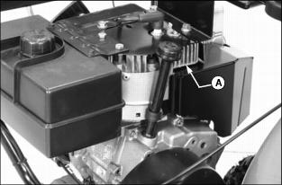
Checking Engine Oil Level
1. Park snowblower on a level surface.
2. Clean area around dipstick.
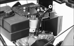
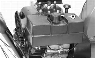
3. Remove dipstick (A). Wipe it off with clean, lint free towel.
4. Install and tighten dipstick. Remove dipstick and locate oil level.
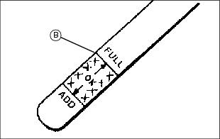
5. Add oil to bring level to the FULL mark (B) on dipstick. (See Engine Oil in this section for correct oil.)
· Add oil through dipstick tube.
6. Install and tighten dipstick.
Changing Engine Oil
NOTE: Change oil after first two operating hours.
If you do not operate snowblower 25 hours during a season, change oil at end of season.
1. Run engine a few minutes to warm oil. Oil will flow more freely and carry away more contamination when warm.
2. Clean area around oil drain plug.
3. Position unit so engine oil drain plug is lowest point on engine.

4. Remove oil drain plug (A) and dipstick (B) to drain engine oil.
5. Install oil drain plug and tighten.
6. Add oil to bring level to the FULL mark (C) on dipstick. (See Engine Oil in this section for correct oil.)
· Add oil through dipstick tube.

7. Install and tighten dipstick.
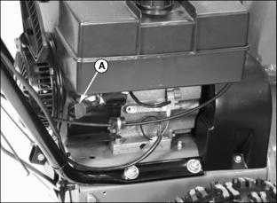
Cleaning And Gapping Spark Plug
1. Clean area around spark plug.
2. Disconnect spark plug wire (A).
3. Remove and inspect spark plug:
· Clean plug and check for damage, replace if necessary.
· If plug is in good condition, check gap.
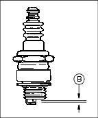
4. Check and adjust spark plug gap (B):
5. Install spark plug and tighten to
20 N·m (15 lb-ft.).
Cleaning Cylinder Fins
· Every 100 operating hours or yearly (more often if conditions require) remove cooling shrouds and clean cooling fins.
· Also clean external surfaces of your engine of dust, dirt, and oil deposits which can contribute to improper cooling.
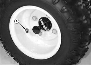
Replacing Shear Bolts
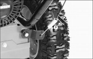
NOTE: Two extra shear bolts were included with your snowblower.

2. Remove broken shear bolt (A), if necessary.
3. Lubricate auger shaft at four points (B). Turn auger shaft several times to distribute grease.
4. Line up holes in auger with hole in auger shaft.
5. Install new shear bolt and lock nut.
Checking Tire Pressure
Check tires for wear or damage, replace as required.
Check tire pressure with an accurate gauge. Tire pressure should be:
· 828D - 138 kPa (20 psi) maximum.
· 1032D - 96 kPa (14 psi) maximum.
Adjusting Carburetor
NOTE: The carburetor is calibrated by the engine manufacturer and should not require any adjustments.
If engine is operated at altitudes above 1829 m (6,000 ft.), see your John Deere dealer.
Possible engine surging will occur at high rpm when the transmission is in neutral ("N") and auger drive is disengaged. This is a normal condition due to the emission control system.
If engine is hard to start or runs rough, check the Troubleshooting section of this manual.
After performing the checks in the troubleshooting section and your engine is still not performing correctly, contact your John Deere dealer.
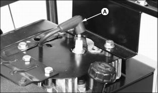
Drain Carburetor
To remove fuel from the carburetor bowl:
1. Turn fuel shut off valve (A) to the CLOSED (OFF) position. (See Fuel Shut Off Valve in Operating section.)
2. Place a small container under the carburetor.
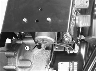
3. Press drain plug (B) in until all fuel is removed from bowl.
Lubricating Auger Gearbox
Check oil level at the beginning of season or every 25 operating hours.
1. Clean area around fill plug.
2. Park unit on level surface.
4. Fluid level should be at oil fill plug.
5. If necessary, add fluid. (See Gear Oil in this section for the correct fluid.)
Lubricating Auger Shaft
Auger shaft should be lubricated at the beginning of season or every 25 operating hours.
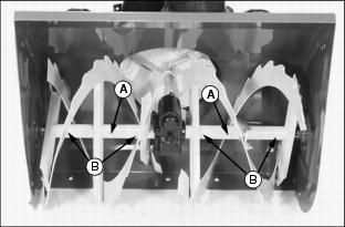
2. Turn auger on shaft while applying grease to grease fittings (B). (See Grease in this section for the correct lubricant.)
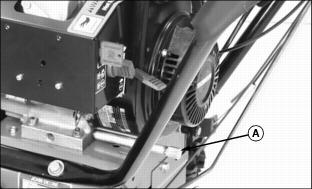
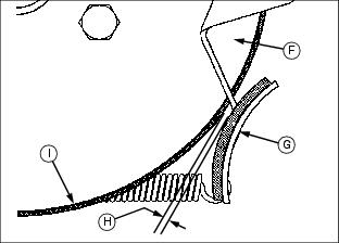
Lubricating Internal Drive
Internal drive should be lubricated at the beginning of season or every 25 operating hours
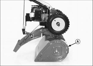
1. Park snowblower on a hard, smooth surface.
2. Stop engine, remove key, wait for all moving parts to stop.
3. Remove wire from spark plug to prevent accidental starting.

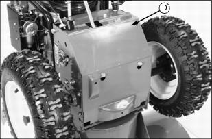
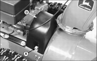
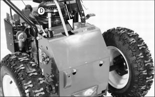
4. Tip machine forward onto housing (A).

5. Remove two bolts (B) and loosen two bolts (C) to remove access panel (D).
IMPORTANT: Avoid damage! DO NOT allow grease or oil to get on friction wheel (E), drive disc or belts. |
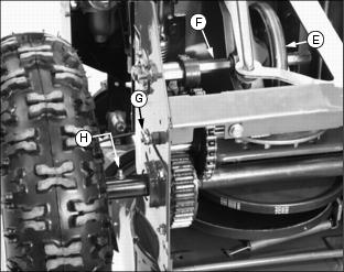
6. Apply grease to hex shaft (F), pinion shaft grease fitting (G) and both drive axle grease fittings (H).
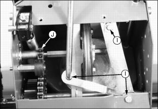
7. Lightly apply oil to shift lever arm pivot points (I) and drive chain (J).
8. Install access panel (D) and tighten hardware.
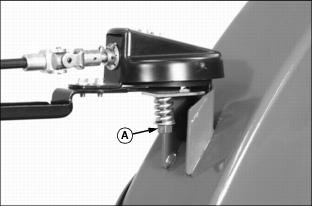
Lubricating Discharge Chute
Discharge chute should be lubricated at the beginning of season or every 25 operating hours.
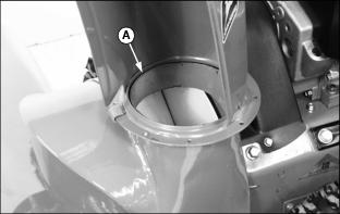
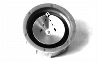
· Turn discharge chute while applying grease to base (A).
Changing Auger Drive Belt
1. Park snowblower on a hard, smooth surface.
2. Stop engine, remove key, wait for all moving parts to stop.
3. Remove wire from spark plug to prevent accidental starting.
4. Tip machine forward onto housing (A).

5. Remove two bolts (B) and loosen two bolts (C) to remove access panel (D). This will prevent the access panel from being bent when unit is split.
6. Tip unit back to it's normal position.
7. Remove quick pull pin (E) and remove chute crank rod (F).
8. Remove both cap screws and lock nuts (G), lay discharge chute assembly off to the right side of the unit.
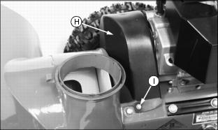
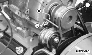
9. Remove two cap screws (I) to remove belt cover (H).
10. Loosen cap screw (J) just enough to loosen belt guide (K).
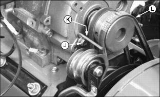
11. Move belt guide enough to remove auger drive belt (L) from engine drive sheave.
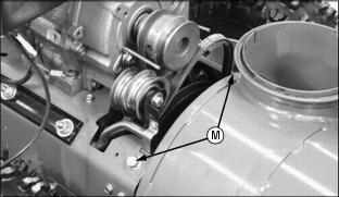
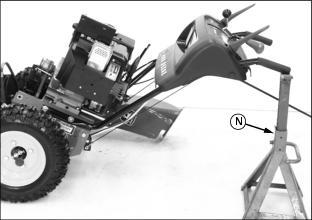
IMPORTANT: Avoid damage! To prevent damage to engine frame and components, hold onto handlebars when removing frame bolts. |

· Place a support (N) under handlebars.
· Remove two cap screws (M) and slowly lean back engine frame.

· Lean back engine frame only far enough to expose the auger drive belt.
· Put handle bars on support (N).
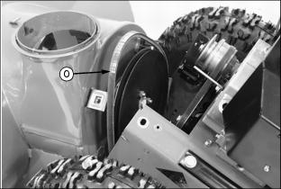
13. Remove auger drive belt (O) and install new belt.
14. Put unit back together and tighten two cap screws (M).
15. Install auger drive belt onto engine drive sheave.
16. Check auger drive belt tension and adjust if necessary. (See Adjusting Auger Drive Belt Tension in this section).
17. Install belt guide and hardware.
18. Install belt cover and hardware.
19. Install discharge chute assembly and connect chute crank rod.
Changing Traction Drive Belt
1. Park snowblower on a hard, smooth surface.
2. Stop engine, remove key, wait for all moving parts to stop.
3. Remove wire from spark plug to prevent accidental starting.

4. Tip machine forward onto housing (A).

5. Remove two bolts (B) and loosen two bolts (C) to remove access panel (D). This will prevent the access panel from being bent when unit is split.
6. Tip unit back to it's normal position.
7. Remove quick pull pin (E) and remove chute crank rod (F).
8. Remove both cap screws and lock nuts (G), lay discharge chute assembly off to the right side of the unit.

9. Remove two cap screws (I) to remove belt cover (H).
10. Loosen cap screw (J) just enough to loosen belt guide (K).
11. Move belt guide enough to remove auger drive belt (L) from engine drive sheave.
IMPORTANT: Avoid damage! To prevent damage to engine frame and components, hold onto handlebars when removing frame bolts. |
· Place a support (N) under handlebars.
· Remove two cap screws (M) and slowly lean back engine frame.
· Lean back engine frame only far enough to expose the drive belts.
· Put handle bars on support (N).
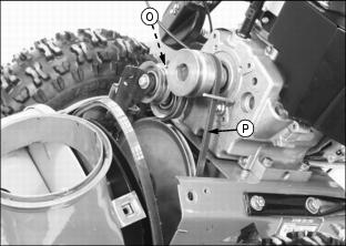
13. Pull back spring loaded idler (O) and remove traction drive belt (P) from engine drive sheave. Install new belt.
14. Put unit back together and tighten two cap screws (M).
15. Install auger drive belt onto engine drive sheave. Check auger drive belt tension and adjust if necessary. (See Adjusting Auger Drive Belt Tension in this section).
16. Install belt guide and hardware.
17. Install belt cover and hardware.
18. Install discharge chute assembly and connect chute crank rod.
Adjusting Auger Drive Belt Tension
Auger drive belt tension should be checked at the beginning of season or every 25 operating hours.
1. Park snowblower on a hard, smooth surface.
2. Stop engine, remove key, wait for all moving parts to stop.
3. Remove wire from spark plug to prevent accidental starting.
4. Remove two cap screws (A) to remove belt cover (B).
5. Hold down the auger drive lever in the engaged position while checking belt tension.
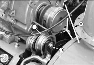
6. Check drive belt deflection (C). Belt should deflect a little with moderate thumb pressure.
· Move pulley (E) toward belt to tighten or away to loosen. Hold pulley and tighten nut.
· Check belt deflection again.
8. When the drive belt is properly tensioned, cable spring should extend approximately 9.5 mm (3/8 in.) (F), with auger drive lever engaged. When the auger drive lever is disengaged, pulley (E) should drop away from the drive belt.
9. Install belt cover and two cap screws.
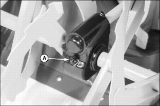
Adjusting Chute Crank
1. Park snowblower on a hard, smooth surface.
2. Stop engine, remove key, wait for all moving parts to stop.
3. Remove wire from spark plug to prevent accidental starting.
· If chute crank is too loose, tighten nut (A).
· If chute crank is too tight, loosen nut (A).
Checking Clutch / Impeller Brake
1. Park snowblower on a hard, smooth surface.
2. Stop engine, remove key, wait for all moving parts to stop.
3. Remove wire from spark plug to prevent accidental starting.

4. Tip machine forward onto housing (A).

5. Remove two bolts (B) and loosen two bolts (C) to remove access panel (D).
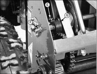
6. Check clearance (H) between brake pad (G) and auger drive belt (I) on auger drive sheave (F):
· With auger drive lever (E) engaged, clearance should be approximately 1.5 mm (1/16 in.).
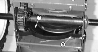
· With auger drive lever (E) released, the brake pad (G) must contact auger drive belt (I).
· If proper clearance can not be obtained see your John Deere Dealer.
Adjusting Chute Deflector Lever
1. Park snowblower on a hard, smooth surface.
2. Stop engine, remove key, wait for all moving parts to stop.
3. Remove wire from spark plug to prevent accidental starting.
4. Check chute deflector lever (A) and adjust if necessary.
To adjust chute deflector lever:
· If lever is too loose, tighten nut (B).
· If lever is too tight, loosen nut (B).
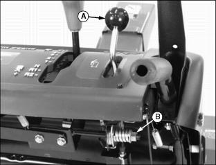
Adjusting Traction Drive Clutch
Adjust traction clutch to compensate for wear of friction wheel when slippage occurs.
1. Park snowblower on a hard, smooth surface.
2. Stop engine, remove key, wait for all moving parts to stop.
3. Remove wire from spark plug to prevent accidental starting.

4. Tip machine forward onto housing (A).
5. Put speed selector lever (B) in FIRST gear.
6. With traction clutch lever (C) DISENGAGED, turn drive wheels by hand. Tighten adjustment nut (D) until wheels begin to drag.
7. Engage and release traction clutch lever (C) to align clutch linkage.
8. Repeat procedure as necessary.
9. When wheel drag is obtained with linkage alignment, loosen adjustment nut (D) a full three turns. Drive wheels will then turn freely.
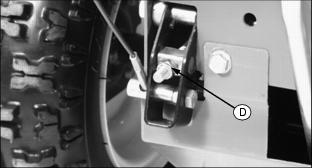
Adjusting Speed / Shift Linkage
1. Park snowblower on a hard, smooth surface.
2. Stop engine, remove key, wait for all moving parts to stop.
3. Remove wire from spark plug to prevent accidental starting.

4. Tip machine forward onto housing (A).
5. Move speed selector lever (B) to the "6" (6th gear) position.
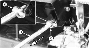
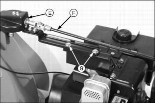
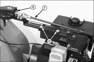
6. Remove quick pull pin (C) from shift rod (D) and remove shift rod assembly from shift lever linkage.
7. Push shift rod (D) into housing as far as it will go and hold it in this position until rod adjustment is made.
8. Turn adjusting link (E) until stud aligns with hole in shift linkage.
9. Install shift rod (D) into shift lever linkage and install quick pull pin (C).
10. Return unit to its operating position.
11. Start engine and check for proper operation of the speed selector lever (B).
Adjusting Drive Chain
1. Park snowblower on a hard, smooth surface.
2. Stop engine, remove key, wait for all moving parts to stop.
3. Remove wire from spark plug to prevent accidental starting.

4. Tip machine forward onto housing (A).

5. Remove two bolts (B) and loosen two bolts (C) to remove access panel (D).
6. Drive chain (E) should be taut with little or no play in it.
7. To adjust chain tightness: Loosen nut (F) and move chain tensioner (G) up or down in slot as necessary.
Fuel
IMPORTANT: Avoid damage! Avoid spilling fuel. Fuel can damage plastic and painted surfaces. DO NOT mix oil with gasoline. Unleaded gasoline with an octane rating of 87 or higher is recommended. |
Dirt in the fuel system is a major cause of performance problems. Be sure to clean the top of the tank before removing lid. Use of a PLASTIC funnel with a plastic mesh strainer when filling the tank will prevent most foreign material from entering the tank.
Regular grade 87 octane unleaded fuel is recommended for use in your snowblower. Higher octane fuels will seldom make your snowblower perform better. If your snowblower develops a starting or performance problem immediately after use of new fuel, change supplier or fuel brand. If the problem still exists after switching fuel, see your John Deere dealer for service.
Fuels are blended to give peak performance during cold weather and warm weather. For cold weather, gasoline is specially blended to provide better starting capabilities. However, avoid prolonged storage of cold-weather blended fuel because it will evaporate more quickly. You may experience longer cranking times in cold weather with "old" fuel. Buy smaller amounts of cold-weather blended fuel in winter.
Fuels used during the summer are not required to provide improved starting properties so they are blended differently. As a result, you may experience hard starting or other performance problems during cold weather if you use fuel remaining from summer uses.
Many areas are now required to add "oxygenates" (either alcohol or ether) which blend oxygen into the fuel to help reduce exhaust emissions. If you use oxygenated fuel be sure it is unleaded and meets the minimum octane rating requirement. DO NOT use fuel that contains methanol to avoid producing excess emissions.
Although fuels blended with alcohol or ether allow your engine to run cleaner, they may contribute to fuel system damage and performance problems by causing gum and varnish deposits, especially if fuel is stored for several weeks or more.
Using clean, fresh fuel will help to prevent damage to the fuel system and will help maintain peak engine performance. If engine performance problems occur, use fuel from another supplier before suspecting machine problems. Suppliers blend fuels differently and changing suppliers will generally solve any performance problems.
The best thing you can do to ensure peak performance of your engine is to use "fresh" fuel. Your snowblower's engine will perform well with most good-quality fresh fuels regardless of additives. Any fuel will begin to deteriorate and evaporate over time and begin to form gum and varnish deposits in the fuel system. Help to avoid this by buying only enough fuel to last approximately 30 days or add fuel stabilizer immediately.
Adding a fuel stabilizer to the fuel system is recommended any time the snowblower will not be operated for more than 60 days. Varnish deposits may build up in the carburetor in as little as a few weeks by using stale, oxygenated fuel.
No stabilizer will work with "stale" fuel, any fuel that is more than 30 days old. (See Preparing Your Snowblower For Storage in the STORAGE section for information on adding stabilizer to the fuel.)
Filling Fuel Tank
1. STOP engine. If engine is hot let it cool several minutes before you add fuel.
2. Remove any dirt and debris from tank area.
4. Fill tank with fresh fuel only to bottom of filler neck.
Cleaning Fuel Cap Vents
· Clean in nonflammable solvent.
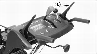
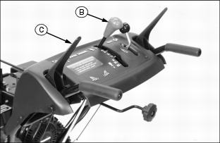
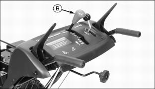
Changing Headlight Light Bulb
1. Stop engine, remove key, wait for all moving parts to stop.
2. Move controls to get more hand room under console:
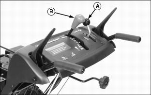
· Move chute deflector lever (A) all the back.
· Move shift lever (B) to the "R2" position.
NOTE: It is not necessary to disconnect the green wire (D) or the black wire (E) to remove the light bulb holder.
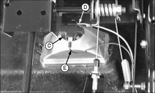
· Turn light bulb holder (C) counterclockwise 1/4 of a turn and remove it from the headlight.
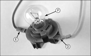
· Turn light bulb (F) counterclockwise 1/4 of a turn and remove it from the holder.
· Remove and replace defective light bulb (F).
· Install light bulb holder. Turn clockwise 1/4 of turn to tighten.