![]()
LX255, LX277, LX277AWS, LX279, and LX288
Introduction
Product Identification
Safety
Operating
Replacement Parts
Service Intervals
Service Lubrication
Service Engine
Service Transmission
Service Electrical
Service Miscellaneous
Troubleshooting
Storage
Assembly
Specifications
Warranty
John Deere Quality Statement
Service Record

Assembly
Install Steering Wheel
1. Put front wheels in the straight forward position.
2. Put John Deere NEVER-SEEZ Lubricant or an equivalent on the steering shaft.
3. Install steering wheel with John Deere logo in the upright position.
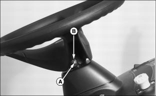
4. Install shoulder bolt (A). Drive bolt in until head of bolt contacts steering wheel.
5. Install washer and nut (B).
6. Tighten lock nut until it is snug. Do not pull washer or head of bolt into steering wheel.
Connect and Check Battery
· Wear eye protection and gloves. · DO NOT allow direct metal contact across battery posts. |
· Battery should be charged if voltage is below 12.3 volts. Battery is fully charged at 12.6 volts.
IMPORTANT: Avoid damage! from cable touching fuel line on LX Models with Air Cooled Engines: |
2. Remove and discard the RED positive (+) protective cap from the positive (+) battery terminal.
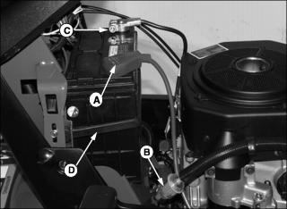
3. On Air Cooled Engines: Route positive (+) cable (A) behind fuel line (B).
4. Turn positive (+) battery clamp inward and connect cable to battery.
5. Connect negative (-) battery cable (C).
6. Apply general purpose grease or silicone spray to terminal to help prevent corrosion.
7. Slide red cover over positive battery cable.
8. Install black rubber strap (D).
Check Engine Oil Level
IMPORTANT: Avoid damage! Remind customer about initial break-in, change engine oil and filter after first 25 hours and 50 hours of operation. |
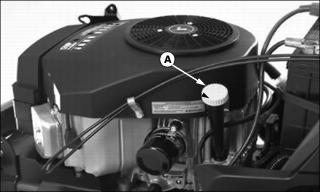
1. Remove dipstick (A) and wipe off with a clean cloth.
· On Kohler or Kawasaki Engines: Install dipstick in tube but, DO NOT tighten dipstick. Let dipstick threads rest on top of tube, rotate cap counterclockwise until it "clicks" or drops into the dipstick tube.
· On Briggs and Stratton Engines: Install and tighten dipstick.
4. Check oil level on dipstick. Oil must be between ADD and FULL marks.
5. If oil level is low, add oil to bring oil level no higher than FULL mark on dipstick.
6. Install and tighten dipstick.